English Русский
Български
Беларускі
Український
Српски
Hrvatski
Română
Polski
Slovenský
Magyar
  |  Articles  |  Sitemap  |  Contacts  |    |
Car maintenance Ford Car maintenance Hyundai Car maintenance Chevrolet Car maintenance BMW Car maintenance Audi Car maintenance Opel Car maintenance AvtoVAZ
VWmanual.ru


Main   Passat   Golf   Polo   Touareg   Tiguan   Sharan   Transporter   Others  
Golf 1 (1974-1984, diesel) Golf 1 (1974-1984, petrol) Golf 2 (1984-1993, petrol) Golf 2 (1984-1993) Golf 3 (1991-1997) Golf 4 (1997-2004) Golf 5 (2003-2008)

Starter repair (VW Golf 2)

  • Main
  • Golf
  • Golf 2
  • Electrical equipment
  • Power devices
  • Starter repair
            0


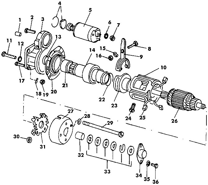
Remove the bolts in front of the retractor relay 5 (figure 447) and disconnect the drive lever to remove the relay.

Figure 447. Starter: 1 - heel pad; 2 - bolt; 3 - back cover; 4 - fork mounting parts; 5 - pull-in…

Figure 447. Starter: 1 - heel pad; 2 - bolt; 3 - back cover; 4 - fork mounting parts; 5 - pull-in relay; b, 15, 35 - spring washers; 7 - nut M8; 8 - lever axis; 9 - lever; 10 - stator winding; 11 - bolt M10; 12, 28 - washers; 13 - thrust ring; 14 - overrunning clutch; 16 - nut MB; 17 - bolt M8; 18 - retaining ring; 19 - nut M8; 20 - bearing cap; 21 - bushing; 22 - spring; 23 - sliding sleeve (not available in 1.3L engine); 24 - pole screw; 25 - carbon brush; 26 - anchor; 27 - manifold cover; 29 - tightening bolt; 30 - spring; 31 - brush holder; 32 - sliding sleeve; 33 - set of washers; 34 - cover; 36 - bolt


Loosen bolts 36 and remove cover 34. Loosen tightening bolts 29.

Remove the retaining rings with a screwdriver, remove the washers from the end of the shaft and remove the starter housing with the stator windings.

Remove the carbon brushes from the brush holder and remove the brush holder. Remove the starter housing from the stator winding. Remove the bolt securing the wire arm and remove the arm.


Remove the gasket from the head, paying attention to its position.

Brushes connected to the stator winding can only be replaced together with the corresponding winding as follows:
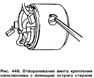
  • loosen the stator pole mounting screws by hitting it with a sharp copper rod, as shown in Figure 448;
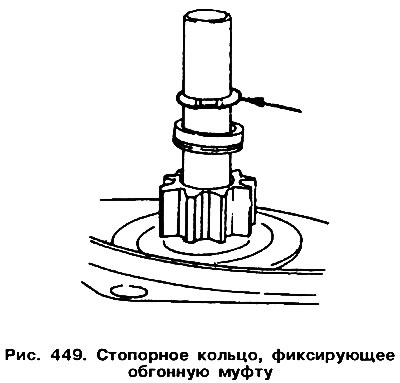
  • remove the poles and windings with brushes. Before removing the anchor or overrunning clutch, remove the retaining ring (arrow in figure 449).
remove the poles and windings with brushes. Before removing the anchor or overrunning clutch,…

[The original material is available on the portal: vwmanual.ru]

Remove the retaining ring from the groove. If necessary, remove burrs from the end of the shaft.

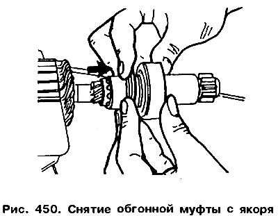
Secure the anchor in a vice and remove the overrunning clutch from the shaft (figure 450).
Secure the anchor in a vice and remove the overrunning clutch from the shaft (figure 450).


All starter parts (except stator) wash in gasoline and check for burnt windings on the anchor and for scratches on the commutator. Small scratches can be removed with very fine sandpaper, large ones should be removed on a lathe. The overrunning clutch cannot be repaired and should be replaced if damaged. The starter is assembled in the reverse order. It should be determined whether the brushes have worn down to the minimum size of 131 mm. If they need to be replaced, the old brushes should be crushed with pliers and the ends of the braided wires should be cleaned. insert into new brushes, flatten from the other side and, holding from below, solder.

When assembling the starter, the following instructions must be followed:

Place the overrunning clutch on the shaft, install the stop ring and a new retaining ring. Rest the stop ring on the press plate (figure 451). Having correctly calculated the pressure on the anchor shaft, insert the retaining ring into the limiting ring.
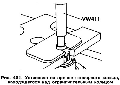
Place the overrunning clutch on the shaft, install the stop ring and a new retaining ring. Rest the…


If you need to replace the manifold bushing (it can be simply removed), then before installing a new bushing, it should be held in hot oil for 5 minutes.

When installing the solenoid relay, care should be taken to ensure that the pusher is correctly connected to the drive lever.

Cover the areas shown in Figure 452 with "D3" sealant.
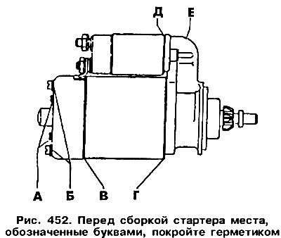
Cover the areas shown in Figure 452 with «D3» sealant.


The axial play of the anchor should be 0.1-0.3 mm. It can be set by changing the thickness of the adjusting washers in the starter housing and the safety C-shaped washer.

This article is available at russian, bulgarian, belarusian, ukrainian, serbian, croatian, romanian, polish, slovak, hungarian
The text has been checked: Kolesnikov Artem

Share information:

Previous articles
Starter replacement
Description and testing of the starter
Possible faults of the battery
Rechargeable battery
Possible generator faults
Motorola Generator Repair
Next articles


Similar articles from other manuals for VW cars:
Removal and installation the fuel starter valve / K-Jetronic… Passat B3 (1988-1993)
Removal and installation the starter (petrol 1.4 l) Polo 3 (1995-2003)
On-board tool, spare wheel, tire repair kit, jack Touareg 1 (2002-2006)
Ignition system repair Tiguan 1 (2007-2015)
General recommendations for car repair Sharan 1 (1995-2000)
Starter — General Information Transporter T4 (1990-2003)
Valve mechanism repair Caddy 3 (2003-2010)
Link to this page in different formats


Visitor comments


No comments yet


How much will 32 + 35 =


Golf 5 
  • General information
  • User manual
  • Maintenance
  • Troubleshooting
  • Power unit
  • Engine repair
  • Cooling and ventilation system
  • Fuel system
  • Ignition system
  • Transmission
  • Clutch
  • Mechanical gearbox
  • Automatic gearbox
  • Chassis
  • Brake system
  • Car suspension
  • Steering
  • Body
  • Interior (internal elements)
  • Exterior (external elements)
  • Doors and covers
  • Electrical equipment
  • Power devices
  • Washers and wipers
  • Lighting and appliances
  • Electrical circuits
Golf 4 
  • General information
  • User manual
  • Weekly checks
  • Maintenance
  • Power unit
  • Petrol engines
  • Diesel engines
  • Cooling system
  • Fuel system (petrol)
  • Control system (petrol)
  • Fuel system (diesel)
  • Exhaust system
  • Transmission
  • Clutch
  • Car gearbox
  • Drive shafts
  • Chassis
  • Car suspension
  • Steering
  • Wheels and tires
  • Brake system
  • Body
  • Exterior (external elements)
  • Interior (internal elements)
  • Ventilation and heating
  • Car doors and sunroof
  • Washers and glass cleaners
  • Electrical equipment
  • Power devices
  • Lighting and appliances
  • Electrical circuits
Golf 3 
  • Petrol engine
  • Engine repair
  • Lubrication system
  • Cooling system
  • Ignition system
  • Diesel engine
  • Engine repair
  • Diesel injection system
  • Pre-glow system
  • Transmission
  • Clutch
  • Gearbox and drive shafts
  • Chassis
  • Steering
  • Wheels and suspension
  • Brake system
  • Electrical equipment
  • Lighting and appliances
  • Electrical circuits
Golf 2 
  • General information
  • Introduction to guide
  • User manual
  • Petrol engines 1.3 l
  • Engine repair
  • Lubrication system
  • Cooling system
  • Carburetors
  • Supply system
  • Ignition system
  • Petrol engines 1.6/1.8 l
  • Engine repair
  • Supply system
  • Ignition system
  • Diesel engines
  • Engine repair
  • Lubrication system
  • Cooling system
  • Power and exhaust system
  • Transmission
  • Clutch
  • 4-speed gearbox 084
  • 5-speed gearbox 085
  • 4-speed gearbox 020/4R
  • 5-speed gearbox 020/4T
  • Automatic gearbox
  • Drive shafts
  • Chassis
  • Steering
  • Car suspension
  • Brake system
  • Body
  • Body elements
  • Doors, locks and windows
  • Electrical equipment
  • Equipment and devices
  • Power devices
Golf 2 (petrol) 
  • General information
  • Characteristics
  • Car care
  • Maintenance
  • Power unit
  • Engine repair
  • Engine 1.05/1.30
  • Engine 1.60/1.80
  • Cooling and lubrication system
  • Power and exhaust system
  • Transmission
  • Clutch
  • Car gearbox
  • Drive shafts
  • Chassis
  • Brake system
  • Steering
  • Suspension
  • Body
  • Body and equipment
  • Electrical equipment
  • Lighting and appliances
  • Electrical circuits
Golf 1 (petrol) 
  • General information
  • Characteristics
  • User manual
  • Maintenance
  • Power unit
  • Engine adjustment
  • Engine 1.1/1.3
  • Engine 1.5/1.6/1.8
  • Engine electrical equipment
  • Cooling system
  • Fuel system
  • Transmission
  • Clutch and manual gearbox
  • Automatic gearbox
  • Chassis
  • Steering
  • Front suspension
  • Rear suspension
  • Brake system
  • Electrical equipment
  • Lighting and appliances
  • Electrical circuits
  • Body
  • Body and equipment
  • Optional equipment
Golf 1 (diesel) 
  • General information
  • Specifications
  • Maintenance
  • Power unit
  • Engine repair
  • Exhaust and turbocharger
  • Cooling system
  • Fuel system
  • Fuel injection system
  • Transmission
  • Clutch and drive shafts
  • Car gearbox
  • Chassis
  • Suspension and wheels
  • Steering
  • Brake system
  • Wheels and tires
  • Body
  • Heating and ventilation
  • Exterior (external elements)
  • Interior (internal elements)
  • Doors and windows
  • Electrical equipment
  • Equipment and devices
  • Lighting system
  • Power devices
  • Electrical circuits
VWmanual.ru © 2016-2026 | Mobile version | News and articles | Sitemap: EN BG BY UA RS HR RO PL SK HU | Write message | Site search
Passat B2 • Passat B3 • Passat B4 • Passat B5 • Passat B6 • Golf 1, diesel • Golf 1, petrol • Golf 2, petrol • Golf 2 • Golf 3 • Golf 4 • Golf 5 • Polo 3 • Polo 4 • Touareg 1 • Tiguan 1 • Sharan 1 • Transporter T3 • Transporter T4 • LT 28 • LT 2D • Beetle • Caddy 3 •
Our website uses cookies to ensure functionality and convenience.