
Lever Replacement
The lever can be disconnected from the steering knuckle in two different ways. At the first, the ball joint is separated from the steering knuckle, at the second I unscrew the bolts of the support to the lever. Both methods are detailed below (see fig. 399).
Loosen the wheel nuts, raise the front of the vehicle, put it on stands and remove the wheel.
Jack up the outer part of the lever (under the hub).
Dismantling the lever in the first way, in which the ball joint remains on the lever:
- Remove the bolt from the knuckle support clamp by carefully knocking it out after removing the nut.
- Remove the side bolt from the front lever arm (the bolt is too tight).
- Then unscrew the lower bolt from the arm of the lever: a metal sleeve will be visible in the hole, which should be removed with tongs.
- Lower the jack and push the lever up until the pivot pin comes out of the hole in the steering knuckle.
- Push the lever at the front out of the mount, and at the rear, pull it out of position between the plate and the subframe.
Dismantling the lever in the second way, in which the bolts securing the support to the lever are unscrewed:
- Outline the ball joint plate at the bottom of the lever so that it will take its previous position during installation.
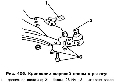
- From below, unscrew the three bolts securing the hinge plate and remove the locking plate with nuts from above (pic. 406).
- Slightly move the spring post outward to disengage the connection.
- Remove the side bolt from the front lever arm (the bolt is too tight).
- Unscrew the lower bolt from the arm of the lever: a metal sleeve will be visible in the hole, which must be removed with tongs.
- Lower the jack and push up on the lever next to the hinge plate.
- Further disassembly steps are described above.
The lever is installed in the reverse order. The tightening torques are given on rice. 399.
Steering knuckle replacement
The steering knuckle can be dismantled after it has been disconnected from the lever in the manner previously described.
Roll Bar Replacement
stabilizer mount (if it is installed in suspension) shown in fig. 407. The stabilizer is connected to the car body by two clamps that cover the rubber liners, and to the suspension arm by means of an articulated rod. When dismantling the stabilizer bar, pay attention to how the parts are installed. The rubber bushings are tapered towards the washers, while the folded edges of the washers should be on the side of the bushings.
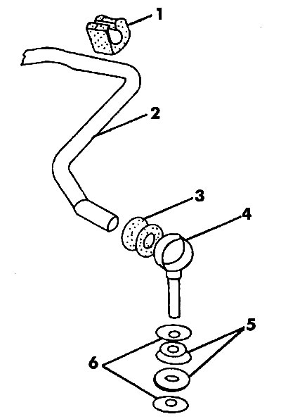
Pic. 407. Anti-roll bar: 1 - pillow; 2 - stabilizer rod; 3 - rubber bushing; 4 - clip; 5 - rubber washers; 6 - metal spacers
Visitor comments