
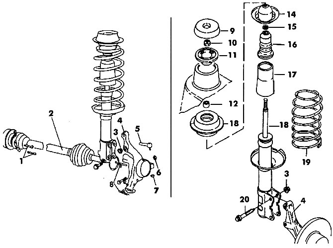
Pic. 398. Front wheel suspension: a - front wheel suspension components; b - spring strut of the front suspension.
1 - bolts (45 Nm); 2 - drive shaft; 3 - nut (50 Nm); 4 - rotary fist; 5 - outer tie rod end; 6 - nut (50 Nm), 7 - hinge nut; 8 - wedges; 9 - cap; 10 - nut M12x1.5; 11 - retaining ring; 12 - castellated nut; 13 - rack support; 14 - upper spring cup; 15 - washer; 16 - rebound buffer; 17 - case; 18 - shock absorber rod; 19 - spring; 20 - bolt M12x1.5
To dismantle the lever, unscrew the drive shaft mounting nut and remove the gasket. Remove the brake disc from the hub. Push the end of the drive shaft out of the steering knuckle, or knock it out with a rubber hammer.
Loosen the nuts and bolts securing the lever to the steering knuckle.
Remove the lever. If necessary, use a large screwdriver, inserting it into the gap at the lever. The lever attachment is shown in fig. 399.
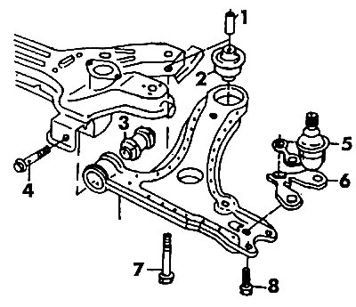
Pic. 399. Mounting the suspension arm: 1 - metal sleeve; 2 - rear rubber-metal bushing; 3 - front rubber-metal bushing; 4 - bolt (130 Nm); 5 - ball bearing; 6 - plate; 7 - bolt (130 Nm); 8 - bolt
To remove the steering knuckle, it is necessary to disconnect the bolts securing the lower part of the spring strut.
Carefully knock out the bolts if they are stuck in the holes.
Take out a screw-driver from space between a rotary fist and a rack and separate them.
Immediately check that the threads are not damaged when the bolts are knocked out.
To dismantle the wheel hub from the steering knuckle, use a press to remove it together with the brake shield (pic. 400). Disconnect the shield. Remove both circlips from the bearing housing.
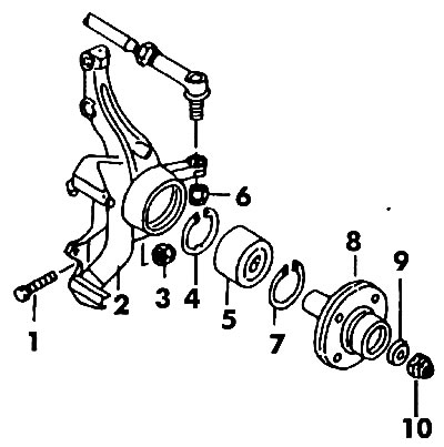
Pic. 400. Front wheel hub (brake shield not shown): 1 - bolt; 2 - rotary fist; 3 - nut M10; 4, 7 - retaining ring; 5 - bearing; 6 - nut M2x1.5; 8 - hub flange; 9 - spring washer; 10 - nut 20x1.5
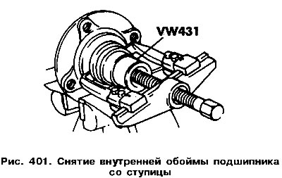
Remove the outer race of the bearing by placing the knuckle under the press with the levers up. The inner race of the bearing remains on the hub and is removed with a special puller (pic. 401).
To dismantle the suspension coil spring and shock absorber, use a spring compressor (pic. 402).
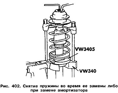
Loosen the nut on the top of the strut. If there is no special key 3078, then loosening the nut will be associated with great difficulties.
Remove the upper support of the spring strut mount, which can only be replaced as an assembly. Remove the top spring cup. Remove suspension spring. There are several varieties of such springs, each type has its own marking with colored marks. At. replacement of springs, both springs must have the same marking. Randomly selected springs cannot be installed, as they are used in vehicles with different weight characteristics.
Remove the rebound buffer from the shock absorber.
Check shock absorber. To do this, secure its lower part in a vise, and then push in and pull out the stem. Throughout the entire stroke of the rod there should be the same resistance. If the shock absorber was laid horizontally, then before installation it should be fixed in a vice vertically and pumped several times.
Visitor comments