
Lever arm. Insert the ball joint pin into the steering knuckle hole and carefully install the mounting bolt. Tighten the new nut to 50 Nm.
Rounded fist. Insert the upper part of the steering knuckle into the spring strut lower mounting bracket and install the bolt holes on the same axle.
Insert both bolts, being careful not to damage the threads. If subsequent measurements show an incorrect camber angle, these bolts will have to be replaced with smaller diameter bolts.
Screw special nuts onto the bolts and tighten them with a torque of 80 Nm.
Suspension spring. Before installing the spring, check whether its anti-corrosion coating is damaged. If both springs were removed, then they should be installed in their original place.
Put the spring on the shock absorber body with a coil of smaller diameter up. Insert the lower end of the spring into the lower cup. Compress the spring with the special tool (rice. 402).
Establish knots and details of the top fastening of a rack (see fig. 398).
While holding the shock absorber rod from rotation, tighten the nut to a torque of 40 Nm.
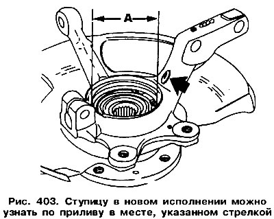
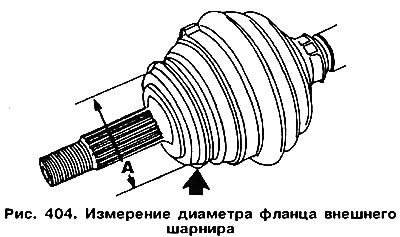
Wheel bearing. Before replacing a wheel bearing or wheel housing, inspect the drive shafts and bearing housing. The design of these parts was changed in 1984. Socket diameter (size «A» in fig. 403) is 68 mm in the new version and 66 mm in the old one. In the new version, the steering knuckle has a tide on the lever, which serves to fasten the rack (arrow in fig. 403). Driveshaft outer pivot diameter changed to accommodate new bearing housing. Therefore, the diameter should be measured «A», shown in fig. 404, which should be 64mm for the new hinge and 62mm for the old one. For a visual distinction of the hinges, the hinge of the old version has a flange with two grooves (see arrow in fig. 404).
When assembling, you can install the bearing housing and the drive shaft joint of the same design.
During the installation of a new bearing, put the retaining ring into the seat, as well as a portion of grease.
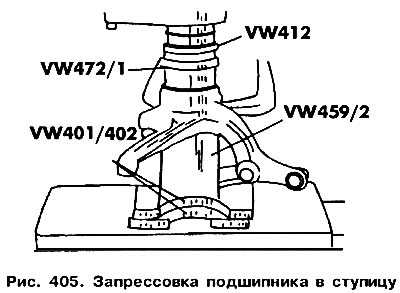
Place the steering knuckle under the press and press in its socket from the outside of the bearing. The steering knuckle must be well supported (pic. 405). It is unacceptable to transfer the press force to the levers of the steering knuckle, which serve to fasten the spring strut. For pressing, use the tools shown in fig. 405. The bearing is pressed in until it contacts the circlip. Install the second retaining ring.
Insert the wheel hub into the bearing. Install the steering knuckle on a piece of pipe that can only rest on the inner race of the bearing. Screw on the brake shield. Install the brake disc.
Visitor comments