



Contents: Disassembly ↓ Installation ↓
Disassembly
To remove the camshaft while the engine is in the vehicle, you must first do the following:
1. Remove the upper timing cover and valve cover.
2. Then remove the timing belt from the camshaft gear.
Note: It is important to remember that before removing the timing belt, the timing marks must be installed. This will make installation much easier. Since it is not necessary to turn the crankshaft or intermediate shaft when removing and installing the camshaft, it is sufficient to install only the mark on the camshaft gear in the correct position later and put the belt on.
3. Remove the camshaft gear.
4. Remove the camshaft bearing caps. They must be put back in the same way and in the same sequence. They are numbered (photo 1.142), but you can make your own markings by stamping dots on the caps. The first cap is closest to the timing gear.
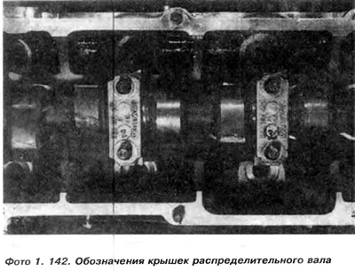
Note: The bearing caps must be gradually unscrewed crosswise in the following sequence: 5-1, 3. Then caps 2 and 4, until the camshaft rises upward under the pressure of the valve springs.
Once the caps are unscrewed, they need to be removed and then the camshaft can be removed. The front seal will be removed along with the shaft.
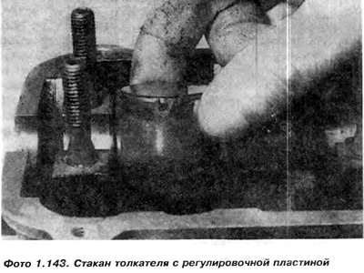
5. The valve lifter cups are now open and can be removed if necessary, for example during head disassembly (photo 1.143). Remove each pusher cup one at a time, then lift the adjusting plate using a small screwdriver and remove it from the cup. The thickness of the plate is written on the back of the plate (for example, 3.75). After recording the plate thickness, cylinder number and valve where it was taken from, it is necessary to insert it into the same cup with the inscription facing down. During installation, the cups must return to their holes. Therefore, a container is needed for each valve assembly and the cup of the pusher with the adjustment plate. Capacities can be designated from 1 to 8.
6. Perform a camshaft check.
Installation
7. Installation is carried out in the reverse order of dismantling.
(The original text is available on the website www.VWManual.ru)
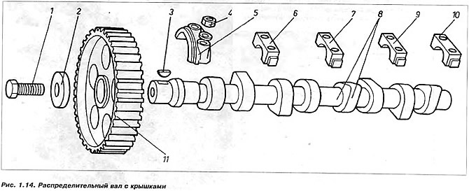
Figure 1.14. Camshaft with covers
1 - bolt securing the timing gear to the shaft; 2 - washer, 3 - tongue; 4 - cover nut; 5 - front cover No.1, 6 - cover No.2, 7 - cover No.3 8 - cover No.4; 10 - cover no. 5; 11 - large timing gear
Visitor comments