
Disassembly
If the head is removed from the engine in the car, it is best to remove it together with the drive and output manifolds. The manifolds can be detached after removing the head. You will need special equipment to disconnect (and then connect) spring clips securing the exhaust pipe to the manifold. To loosen and tighten the engine head bolts, you will need a special wrench.
1. Disconnect the wire to the battery ground. Drain the liquid from the cooling system, then disconnect the elastic pipes of the cooling system and heater from the engine head.
2. Disconnect the wires from the oil temperature and pressure sensor.
3. On carbureted models, remove the air cleaner assembly.
4. Unscrew the alternator from the brackets securing the engine head and remove the V-belt.
5. Unscrew and remove the drive and exhaust manifolds, although it is possible to disconnect the manifolds after removing the engine head. When removing the manifolds together with the engine head, disconnect the thin air flexible pipe (reduced pressure) from the drive manifold, as well as the gas cable (and starting equipment damper cable, if equipped) from the carburetor.
6. To remove a cover of the distributor of ignition together with wires of ignition.
Attention: In models equipped with fuel injection, you must additionally:
7. Disconnect the nozzles of the injector from the engine head, as well as their mounting clips and move to the side so as not to interfere.
8. Disconnect the elastic drive tube from the throttle body.
9. Disconnect the flexible low pressure pipes from the throttle body. Set aside the pipes so that they do not interfere.
10. Disconnect the secondary air valve connection from the bottom) drive manifold and an additional air valve flexible pipe from a flexible pipe on the throttle valve body.
11. Disconnect the low pressure flexible hose from the green connector on the throttle body.
12. If the car is equipped with air conditioning, disconnect the flexible pipes from the auxiliary air valve and the connections of the fixed pipes.
13. Disconnect the flexible tube of the vacuum gauge.
14. Disconnect the cube from the cold start valve (winter).
15. Remove the timing cover and valve cover, then remove the timing belt from the camshaft gear.
16. To take out a camshaft.
17. The next step is to remove the bolts and the engine head. A special wrench must be used to unscrew them. If a hex wrench is used, there is a high probability that the socket in the bolt head will be destroyed and then it will be impossible to unscrew the bolt if it is not drilled.
18. Bolts of a head of the engine have to be turned away gradually in sequence, the return specified on fig. 1.6. First you need to loosen all the bolts by half a turn, and then unscrew them.
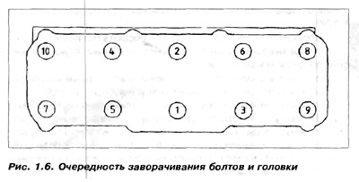
19. After removing all 10 bolts, remove the head from the cylinder block. If it is stuck to the block, you need to lightly tap with a hammer and a wooden mallet.
Under no circumstances should any tool be driven in between the cylinder head and the cylinder bolt, as the surface of the cylinder head or block may be damaged.
Scratches or indentations that appear will make it impossible to seal the head and it will be necessary to grind the damaged surface at a specialized company. You can also pull hard on the manifolds and tear off the head.
20. Remove the gasket from the cylinder block.
Usually part of the gasket sticks to the block and head. It is necessary to carefully clean the surfaces of the pistons and the smooth surface of the block.
Repair
21. Clean the bottoms of the pistons from carbon deposits. Remove spark plugs. Then, using a metal brush and a scraper, remove carbon deposits from the combustion chambers and valve surfaces. Rinse the head cleaned from soot with water and blow it with compressed air.
22. The valves can only be removed easily with the proper valve spring compression equipment. Since the conical safety rings and the upper spring plates are set deep enough in the head, disassembling the valves without a tool is almost impossible. If there is no such equipment, it is necessary to find a short metal tube with a diameter of approximately 25 mm and press the valve spring plate down. e.g. with the stand of a drilling machine. The length of the tube will depend on the size of the compression equipment. Cut two rectangular holes, about 25 mm long and 16 mm wide, on opposite sides of the tube. Insert cone fuses through the holes. This tube can then be used in conjunction with a compression tool when the safety catch is removed from successive valve stems.
The valve, springs, fuses and plates must be contained together with the pusher in the same container so as not to be mistaken during assembly. It is best to number the containers from 1 to 8, keeping in mind that valve #1 is closest to the distribution belt.
23. Actions to be performed in order to verify and repair the head.
24. Before mounting the engine head, check the condition of the camshaft.
25. When we have verified all parts, heads, valves, springs, guides, seals and camshaft, we can proceed with the installation of the head.
Installation
Insert the valve into the desired guide. Before installation, the valve stem must be lubricated with oil. Assemble the spring compression equipment with the tubing prepared and compress the valve spring so that the cones can be inserted into the valve stem groove. If this is difficult to do by hand, you can put some grease on the guard and use a small screwdriver or tweezers to insert it through the hole in the tube onto the valve stem. Put on the second half of the protection and, holding it, carefully release the spring compression equipment until. until the plate presses the conical half rings to the grooves. Remove the spring compressor, put a rag on the valve stem and hit the stem several times with a hammer. In this way, we will check whether the protection is well seated in the groove. If it entered the groove incorrectly, then it will come out upon impact. It must be remembered that the valve into which we will hit with a hammer is free, not supported by anything and moves freely in the guide. These steps must be repeated for all eight valves.
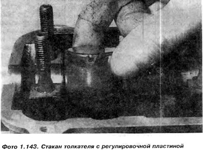
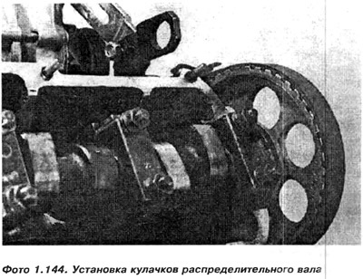
26. Insert the oil-coated tappets into the holes from which they were removed along with the shims (photo 1. 143), then lubricate the surfaces of the camshaft bearings and fix the camshaft so that the lobes of the cams of the first cylinder are set upwards (photo 1. 144)
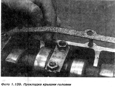
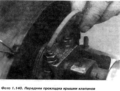
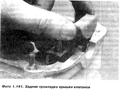
27. Install a new seal on the side of the timing gear Lubricate the shaft journals, as well as No. 2 and No. 4 (photo 1. 142). Then mount the rest of the earbud covers, making sure they are properly fitted (according to the dot designation made during dismantling) and tighten the nuts of all covers with the appropriate moment. Install a new set of head cover gaskets (photo 1.139, 1.140 1.141).
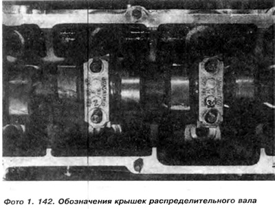
Attention: We press the camshaft covers evenly so as not to cause very strong stresses in the shaft, which can distort it. First, it is necessary to press the covers closest to the valves, which the shaft must bend during compression.
28. Adjust valve clearances.
Installing the head on the engine
29. Mounting the head on the engine.
Visitor comments