
Unscrew the head of the lever, pull the cover up and remove it.
Loosen the shifter bolts. The rack must be adjusted so that its centering holes coincide with the holes of the plate lying below.
Check whether the holes in the switching rack match exactly with the threaded holes for the bolts.
If ist, rotate the stand 180 degrees and securely fasten.
Raise the car and place it on stands.
Unclip the clamp at the switching rod - lever connection. The shift bar must move freely in the shift lever guide.
At the bottom of the switching unit housing, remove the cuff.
lever position in "neutral" must be such that the switch pin in the longitudinal direction is located exactly in the middle of the housing.
For lateral adjustment of the lever, a 20 mm wide cardboard template is required for a four-speed gearbox, and a 15 mm wide cardboard template for a five-speed gearbox.
Rotate the switch rod in such a way that the named gap is maintained ("A" in fig. at the bottom) between switch pin and bottom edge of housing
Securely lock the clamp in this position.
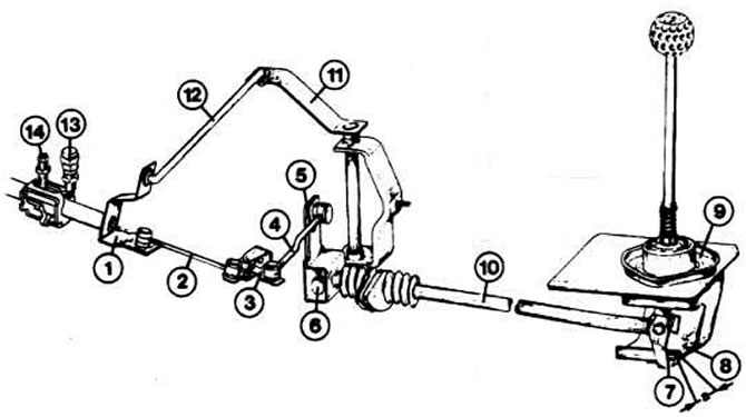
Details of the shift assembly of the five-speed gearbox: 1 - switch shaft lever; 2 - control rod in front; 3 - rotary corner; 4 - control rod at the back; 5 - control lever; 6 - rotary lever; 7 - switching finger; 8 - thrust sheet; 9 - switch lever support; 10 - switching rod; 11 - rotary shaft; 12 - connecting washer; 13 - locking screw for 5th gear; 14 - locking screw for the switching shaft. Distance "A" should be equal to 20 mm for a four-speed and 15 mm for a five-speed gearbox
Visitor comments