
Attention! When replacing engines, gearboxes and clutches, make sure that the diameters of the decouplers and diaphragm springs match.
Removing
Disconnect clamp "frame" from the battery.
Remove the upper part of the air filter, to do this, remove the snorkel, give 6 clips and pull out the upper part of the filter.
Remove the bottom engine cover. To do this, remove the 3 cross-head bolts at the top front and 5 screws at the rear. Unscrew 2 nuts on the right and left.
Set the heating lever on the instrument panel to "warm".
Remove the lock on the cooling system surge tank. The surge tank is located, when viewed in the direction of travel, to the right of the battery.
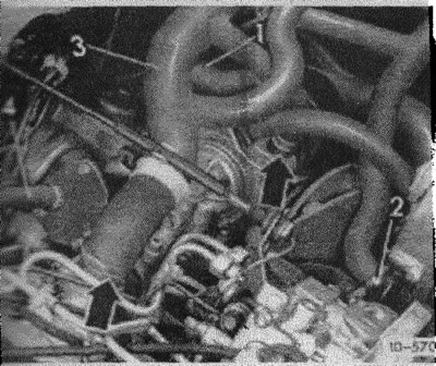
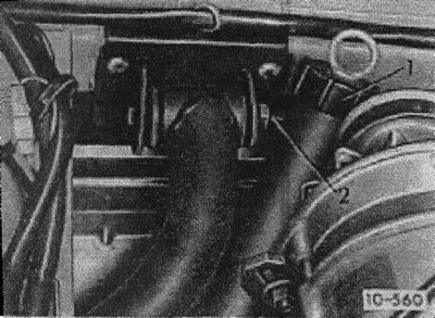
Remove cooler. To do this, remove the lower hose of the cooling radiator from the connecting tube (1) radiator, and also remove the middle hose (2) on the cooling pump. The clamps must be fully opened and pushed back.
Attention! The cooler must be collected for further use.
- hose (3) Disconnect from cylinder head and oil cooler and fold to one side.
- low pressure hose (4) remove from the vacuum pump.
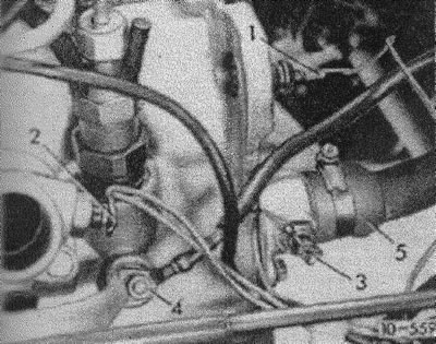
- (10-559) oil pressure regulator electrical wires (1), temperature sensor (2) And (3), as well as glow plugs (4) mark and disconnect.
- hose (5) take off.
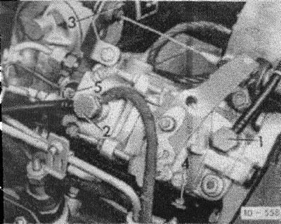
- (10-558) supply (transparent) handset (1) and outlet (with an inscription "OUT") (2) unscrew at the fuel pump.
- unhook the linkage on the fuel pump lever. Pull out the stopper on the counterholder (3) and take off the pull.
- bolt-on cold start rod (4) release, remove the stopper on the counterholder and pull out the rod.
- electrical wire (5) disconnect from the switch.
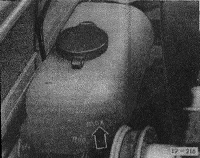
- (19-216) Disconnect the connecting hose from the surge tank and plug it with a suitable plug.
- remove the coolant fill tank.
- (10-560) models up to 8.82: unscrew nuts (2) engine bracket, rear right and left. Attention! Leave the bolts!
- models from 8.82: Remove the oil pickup.
- (10-571) connecting screws (1) (7 pieces) unscrew.
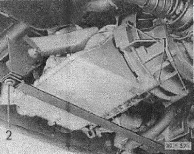
- models up to 8.82: unscrew the traction band (2).
- remove the electrical wire from the generator, for which release the wire clamp.
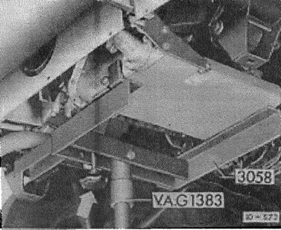
- (10-572) Support the engine with a jack and engine mount. The angle of the motor can be adjusted with the set screw shown by the arrow.
- if special tools are not available, then install a jack with a wide wooden support under the engine.
- (10-573) models up to 8.82: front right and left, unscrew the nuts of the engine bracket, shown by arrows. Remove bolts front and rear.
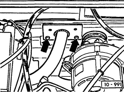
- (10-991) models from 8.82: unscrew both engine brackets front and rear from the structure (see arrows)
- to lower the engine together with the gearbox to such a level, it would be possible to separate the engine from the gearbox.
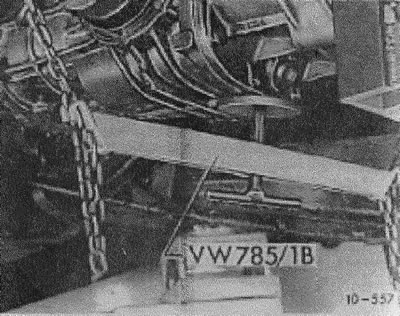
- (10-557) support the gearbox with a special stop device. Hang the locking device and lift up to the gearbox.
Attention! If a locking device is not available, the gearbox can be supported with a jack or support rings, do not forget the wooden lining).
- pull the engine out of the transmission housing and move downwards.
Installation
Before installation, the following operations must be carried out: Thoroughly clean the gear housing and motor flange. Only wipe the connecting-disconnecting bearing, do not wash the legs in gasoline or other cleaning agents.
- Check the release bearing for wear and replace if necessary. Cover the plastic ring with some paste.
- Lubricate the starting shaft bushing with a small amount of universal grease.
- Finely splined profile of the drive shaft of the reducer is coated with MoS2 powder.
- check clutch disc alignment (see section "Clutch").
- set to 1st gear so that the gearbox input shaft does not turn.
- install the engine on a special receiver and insert it into the engine compartment.
- angle of inclination of the engine relative to the gearbox to set using the adjusting screw (10-572), shown by an arrow.
- connect the flanges of the engine and gearbox.
- in the absence of special tools, install the motor on a mobile jack with a wooden stand.
- using assistants, lift the engine into the engine compartment. At the same time, direct the engine from above. The input of the engine must be done with great care so as not to deform the clutch disc, which is disconnected under the drive shaft.
- when pushing the engine, it is necessary to simultaneously turn the V-belt pulley back and forth so that the crankshaft rotates a little and the teeth of the drive shaft enter the clutch disc better.
- connect the engine closely to the gearbox. Insert engine and gearbox mounting bolts and tighten firmly. Tighten M12 bolts with a torque of 80 nm, M10 with a torque of 45 nm.
- lift the engine and box, insert the bolts into the engine brackets.
- models up to 8.82: use new self-locking nuts to fix the motor on the brackets. Tighten the bracket with a torque of 85 Nm. Then tighten the traction band with a torque of 45 Nm.
- models from 8.82: screw the engine brackets to the structure, tightening all the bolts with a torque of 24 Nm.
- Attach the electrical wire to the generator and secure with a wire clamp.
- install coolant filling tank, put hose on leveling tank.
- install and adjust the cold start rod.
- connect and adjust the gas draft.
- connect the electrical wires to the switch, glow plugs, oil pressure regulator and temperature sensor (2 pieces).
- Push the low pressure hose onto the vacuum pump and secure with a clamp.
- Screw the fuel lines to the fuel pump and tighten to 25 Nm. Do not confuse inlet and outlet!
- the return line has a smaller diameter and is marked on the hexagonal head with the inscription "OUT".
- put on all cooler hoses and secure with clamps.
- install cooler.
- install the engine cover.
- put on the upper part of the air filter and fasten the 6th za-mi, attach the snorkel.
- attach the battery to the case
- check the oil level in the engine.
- start the engine and check the tightness of the water and fuel hoses.
- after reaching operating temperature (oil temperature 60 deg.) Check water level, top up if necessary.
Visitor comments