
English Русский
Български
Беларускі
Український
Српски
Hrvatski
Română
Polski
Slovenský
Magyar
  |  Articles  |  Sitemap  |  Contacts  |    |
Car maintenance Ford Car maintenance Hyundai Car maintenance Chevrolet Car maintenance BMW Car maintenance Audi Car maintenance Opel Car maintenance AvtoVAZ
VWmanual.ru


Main   Passat   Golf   Polo   Touareg   Tiguan   Sharan   Transporter   Others  
LT 28 (1975-1991) LT 2D (1996-2003) Beetle (1960-1986) Caddy 3 (2003-2010)

Rear brake pads — inspection and replacement (VW Lt 28)

  • Main
  • Volkswagen
  • LT 28
  • Chassis
  • Brake system
  • Rear brake pads — inspection and replacement
            0


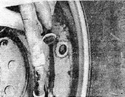
1. The wear of the rear brake pads can be determined by looking through a small hole in the rear brake plate (see photo 7.1).

Photo 7.1. Removing the plug from the hole to check the brake pads.

Photo 7.1. Removing the plug from the hole to check the brake pads.


2. If the friction material is worn to the minimum thickness or even less than specified in the Specifications, the pads should be replaced on both wheels (four pieces).

3. Raise the vehicle and remove the rear wheels.

4. Loosen the drum mounting screw and remove the drum. If it is tight, insert a screwdriver into the hole in the rear brake plate and turn the adjuster sprocket back (see photo 7.4).
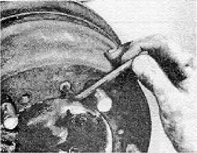
Photo 7.4. Unscrewing the drum mounting screw.

Photo 7.4. Unscrewing the drum mounting screw.


5. Loosen the handbrake cable by unscrewing the nuts on its equalizer.
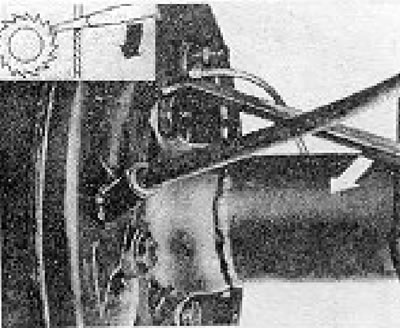


Figure 9.15. Loosening the rear brake shoe adjuster (Section 7).

Figure 9.15. Loosening the rear brake shoe adjuster (Section 7).


6. If the drum is still stuck, use three M10 x 40 bolts, screwing them in and three specially cut holes to disconnect the drum.
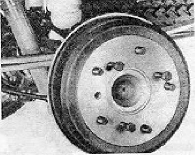
Figure 9.16. Using bolts to remove the brake drum (Section 7).

Figure 9.16. Using bolts to remove the brake drum (Section 7).


7. Disconnect the handbrake lever from the brake shoe (see photo 7.7).
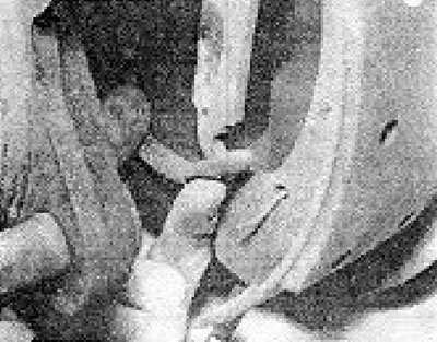
Photo 7.7. Disconnecting the handbrake cable from the brake shoe lever.

Photo 7.7. Disconnecting the handbrake cable from the brake shoe lever.


8. Remove the brake shoe stability springs (see photo 7.8). To do this, press on the spring seat with pliers and rotate it 90°. Remove the seat, spring, and pin.
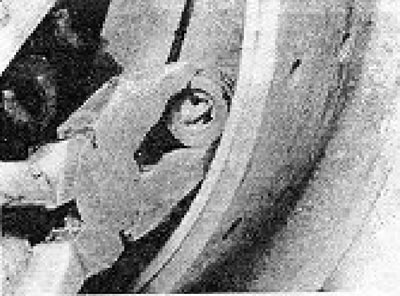
Photo 7.8. Removing the brake shoe stability spring seat.

Photo 7.8. Removing the brake shoe stability spring seat.


9. Disconnect the lower spring of the shoe and remove the lower ends of the shoe from their fastenings in a forward direction (see photo 7.9).
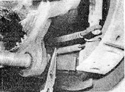
Photo 7.9. Disconnecting the lower spring of the shoe.

Photo 7.9. Disconnecting the lower spring of the shoe.


10. Disconnect the spring from the automatic regulator lever (see photo 7 10).
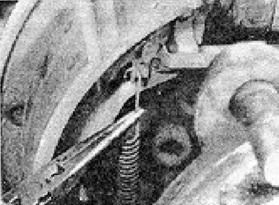
Photo 7.10. Disconnecting the automatic regulator lever spring.

Photo 7.10. Disconnecting the automatic regulator lever spring.


11. Release the lower ends of the pads completely.

12. Disconnect the upper brake shoe return springs.
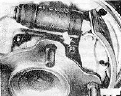
Figure 9.17. Upper brake shoe return springs (Section 7).

Figure 9.17. Upper brake shoe return springs (Section 7).


13. Note how exactly the pads are installed relative to the leading and trailing ends (areas of the pad not covered with friction material).

14. Remove the pads and automatic regulator.

15. After removing the pads, do not press the brake pedal under any circumstances, otherwise the pistons may fall out. It is recommended to hold the pistons in the cylinders with a rubber band if they are expected to fall out.

16. Wipe and clean all dust and dirt from the back plate and inside the drum. Be careful not to blow away this dust as it contains asbestos, which is hazardous to health (see photo 7.16).
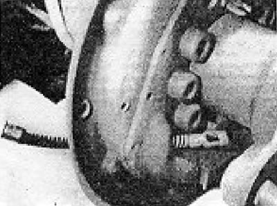
Photo 7.16. Rear brake plate after removing the pads.

Photo 7.16. Rear brake plate after removing the pads.


17. The new pads will immediately be supplied with new levers riveted into place. Install the original automatic regulator stand onto the new pads (see photo 7.17 a and b).
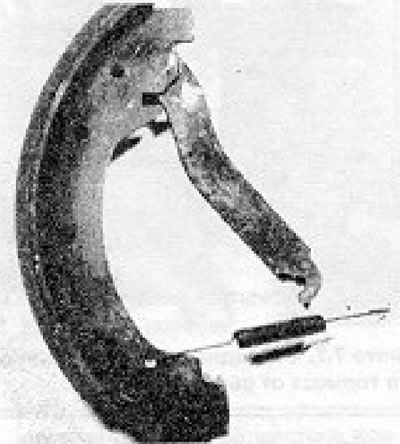
Photo 7.17a. Handbrake shoe with lever.
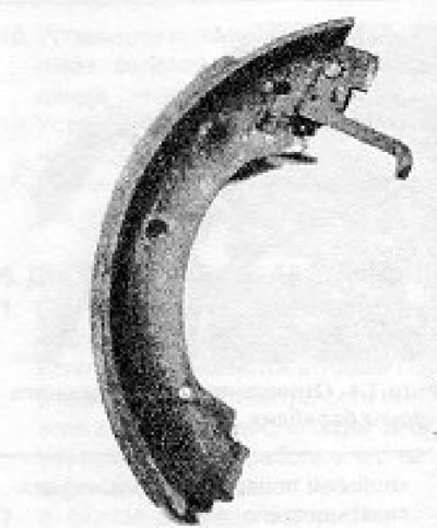
Photo 7.17a. Handbrake shoe with lever.


Photo 7.17b. Shoe with automatic regulator lever.

Photo 7.17b. Shoe with automatic regulator lever.


18. Install the pads, aligning their upper ends with the pistons.
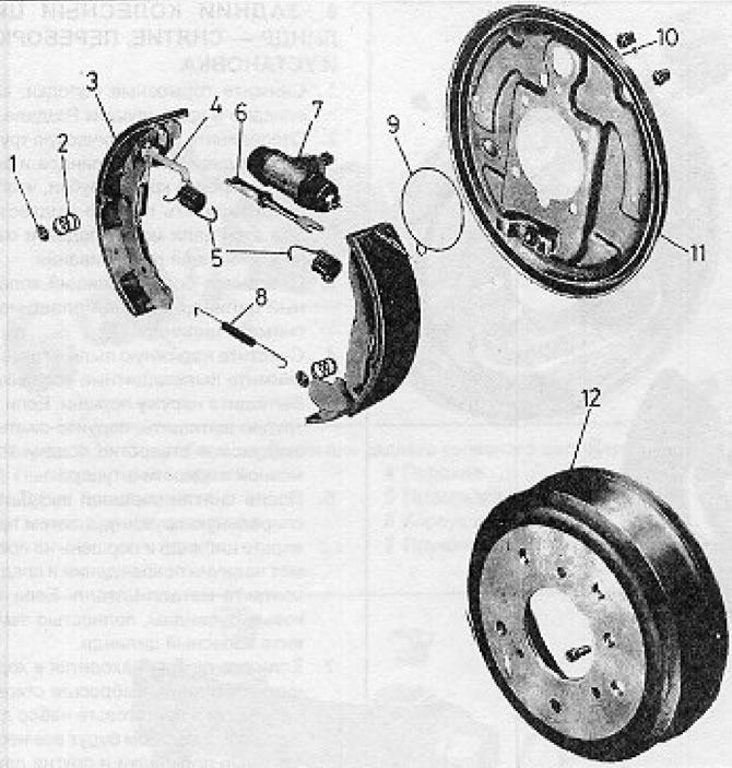
Figure 9.13 Rear brake components (models LT 23, 31) (Section 7): 1 - Brake shoe stability washer;…

Figure 9.13 Rear brake components (models LT 23, 31) (Section 7): 1 - Brake shoe stability washer; 2 - Brake shoe stability spring; 3 - Block; 4 - Automatic regulator lever; 5 - Upper return springs; 6 - Automatic regulator stand; 7 - Wheel cylinder; 8 - Lower return spring; 9 - O-ring; 10 - Pad pin; 11 - Back plate; 12 - Drum.
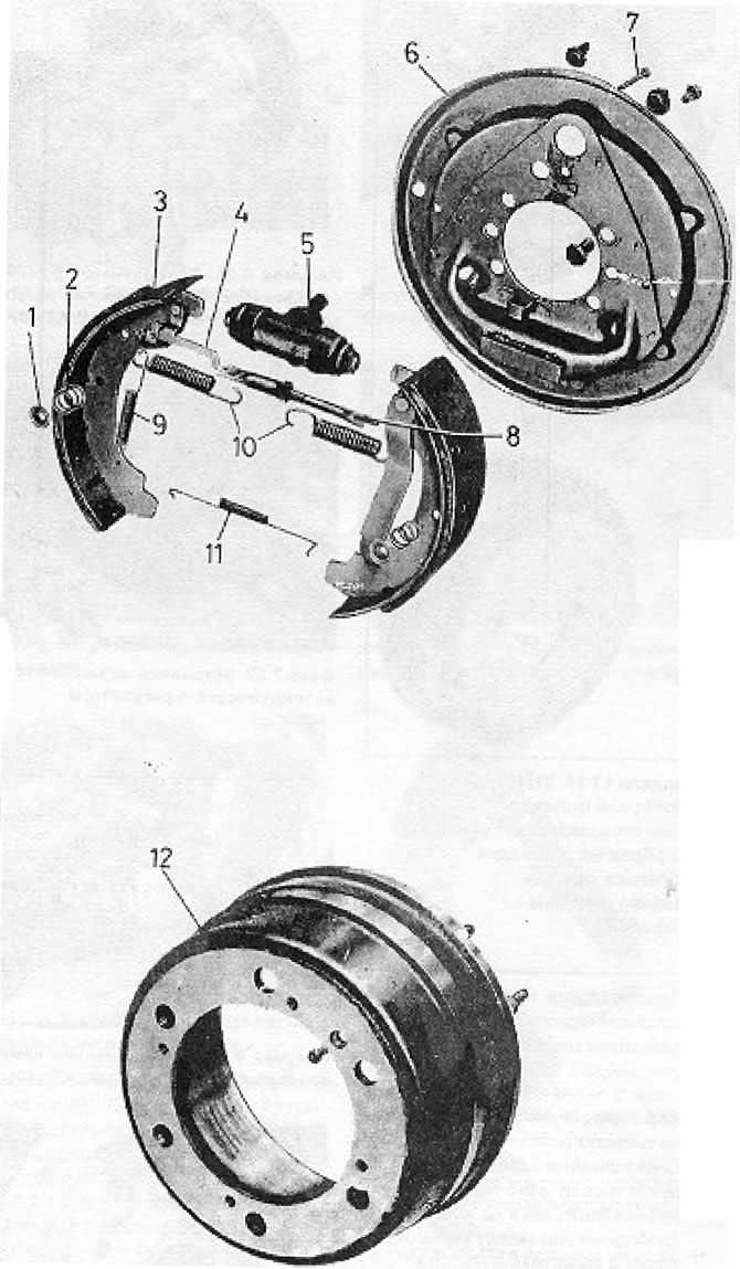

Figure 9.19. Rear Brake Components (LT 35) (Section 7): 1 - Brake shoe stability washer; 2 - Brake…

Figure 9.19. Rear Brake Components (LT 35) (Section 7): 1 - Brake shoe stability washer; 2 - Brake shoe stability spring; 3 - Block; 4 - Automatic regulator lever; 5 - Wheel cylinder; 6 - Back plate; 7 - Pad pin; 8 - Automatic regulator stand; 9 - Automatic regulator lever spring; 10 - Upper return springs of the shoe; 11 - Lower return spring of the shoe; 12 - Drum.
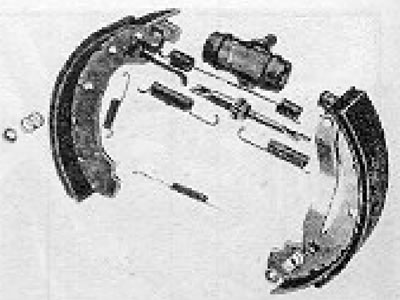

Figure 9.20. Return springs of the shoe and its automatic regulator of a different type on the LT…

Figure 9.20. Return springs of the shoe and its automatic regulator of a different type on the LT 40, 45 models (Section 7).


19. Install the upper return springs and secure them to the ends of the rear plate protrusions. It should be noted that the fastening of the ends of the springs varies depending on the car model. Note also that the LT 40 and 45 versions have additional upper springs (refer to the corresponding illustrations).

20. Insert the lower ends of the pads into the mounts.

21. Clean the automatic regulator lever and lightly lubricate its threads.

22. Spread the pads apart using a screwdriver and insert the adjuster lever between them (see photo 7.22).
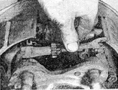
Photo 7.22. Installing the automatic regulator stand in place.

Photo 7.22. Installing the automatic regulator stand in place.


23. Attach the lower return springs to the shoes.
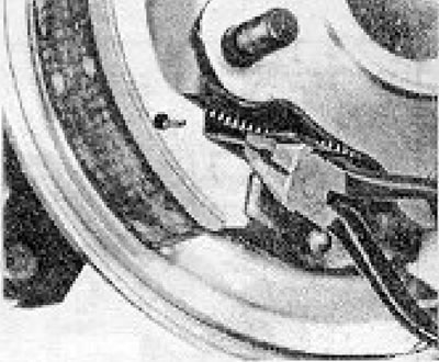
Figure 9.21. Attaching the lower brake shoe return spring (Section 7).

Figure 9.21. Attaching the lower brake shoe return spring (Section 7).


24. Install the springs and brake shoe stability seats.

25. Connect the handbrake cable to the brake shoe lever and make sure it hangs freely.
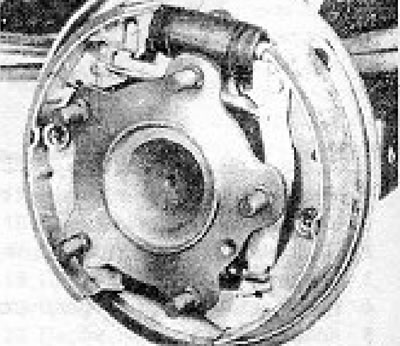
Figure 9.22. The handbrake cable adjusted to eliminate the gap at the point indicated by the arrow…

Figure 9.22. The handbrake cable adjusted to eliminate the gap at the point indicated by the arrow (Section 7).


26. Attach the spring to the automatic regulator lever.

27. Visually center the shoes in relation to the rear brake plate, then turn the sprocket on the adjuster lever until the drum can pass over the shoes.

28. Remove the drum again and adjust the handbrake cable on the equalizer until there is no more free play between the shoe lever and the adjuster lever.

29. Install the drum and wheel and lower the vehicle to the ground.

30. Apply the handbrake several times to fully seat the brake pads in the drum using the automatic adjuster mechanism.

This article is available at russian, bulgarian, belarusian, ukrainian, serbian, croatian, romanian, polish, slovak, hungarian
The text has been checked: Kolesnikov Artem

Share information:

Previous articles
Disk — check and replace
Brake shoe (caliper) — removal, overhaul and installation
Hydraulic Components — disassembly (general information)
Brake disc pads — inspection and replacement
Maintenance and adjustment
Description of the braking system
Next articles
Rear wheel cylinder — removal, overhaul and installation
Master Brake Cylinder — removal, overhaul and installation
Pressure regulating valve — checking and adjustment
Flexible and rigid hydraulic lines — inspection and replacement
Hydraulic system — bleeding
Vacuum booster — removal and installation


Similar articles from other manuals for VW cars:
Checking the rear brake pads Passat B5 (1996-2005)
Replacing rear drum brake pads Golf 1 (1974-1984, petrol)
Removal and installation rear disc brake pads Polo 4 (2001-2009)
Adjusting brake pads on two wheels Touareg 1 (2002-2006)
Removal and installation rear brake pads CII41 Tiguan 1 (2007-2015)
Checking the thickness of the rear brake pads Sharan 1 (1995-2000)
Rear drum brake, brake lining control Transporter T3 (1979-1992)
Link to this page in different formats


Visitor comments


No comments yet


How much will 39 + 42 =


Caddy 3 
  • General information
  • User manual
  • Daily care
  • Maintenance
  • Petrol engines 1.4 l
  • Engine repair
  • Cooling and lubrication system
  • Power and exhaust system
  • Petrol engines 1.6 l
  • Engine repair
  • Cooling and lubrication system
  • Power and exhaust system
  • Diesel engines
  • Engine repair
  • Cooling and lubrication system
  • Power and exhaust system
  • Transmission
  • Mechanical gearbox 0AH
  • Mechanical gearbox 0A4
  • Drive shafts
  • Chassis
  • Car suspension
  • Steering
  • Brake system
  • Body and wiring diagrams
  • Interior and exterior
  • Electrical circuits
Beetle 
  • General information
  • Maintenance
  • Power unit
  • Engine repair
  • Cooling and lubrication system
  • Supply system
  • Exhaust system
  • Transmission
  • Clutch
  • Car gearbox
  • Chassis
  • Front suspension
  • Rear suspension
  • Steering
  • Brake system
  • Wheels and tires
  • Body
  • Exterior
  • Electrical equipment
  • Equipment and devices
  • Power devices
  • Electrical circuits
LT 2D 
  • General information
  • User manual
  • Maintenance
  • Power unit
  • Petrol engines 2.3 l
  • Diesel engines 2.5 l
  • Diesel engines 2.8 l
  • Injection system (diesel 2.8 l)
  • Transmission
  • Clutch
  • Manual gearbox
  • Differential
  • Chassis
  • Car suspension
  • Steering system
  • Brake system
  • Body
  • Body elements
  • Heating system
  • Electrical equipment
  • Equipment and devices
  • Electrical circuits
LT 28 
  • General information
  • Maintenance
  • Power unit
  • Petrol engines 2.0L
  • Petrol engines 2.4L
  • Diesel engines
  • Cooling and heating
  • Fuel and exhaust system
  • Ignition system
  • Transmission
  • Clutch
  • Car gearbox
  • Cardan shaft
  • Rear axle
  • Chassis
  • Brake system
  • Car suspension
  • Steering system
  • Body
  • Body elements
  • Doors, locks and windows
  • Electrical equipment
  • Power devices
  • Equipment and devices
  • Electrical circuits
VWmanual.ru © 2016-2026 | Mobile version | News and articles | Sitemap: EN BG BY UA RS HR RO PL SK HU | Write message | Site search
Passat B2 • Passat B3 • Passat B4 • Passat B5 • Passat B6 • Golf 1, diesel • Golf 1, petrol • Golf 2, petrol • Golf 2 • Golf 3 • Golf 4 • Golf 5 • Polo 3 • Polo 4 • Touareg 1 • Tiguan 1 • Sharan 1 • Transporter T3 • Transporter T4 • LT 28 • LT 2D • Beetle • Caddy 3 •
Our website uses cookies to ensure functionality and convenience.