



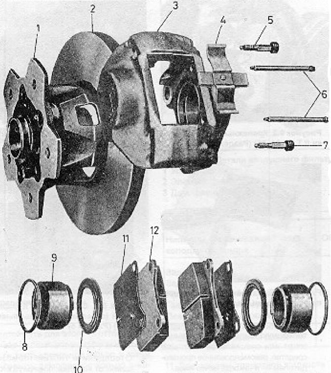
Figure 9.7. Detailed view of a typical brake pad (caliper) (Section 5): 1 - Hub; 2 - Disc; 3 - Block (caliper); 4 - Spring for limiting the travel of the linings; 5 - Upper bleeder bolt; 6 - Mounting studs for linings; 7 - Lower bleeder bolt; 8 - Piston gasket; 9 - Piston; 10 - Dust cap; 11 - Piston mount; 12 - Disc lining.
1. Raise the front of the vehicle and remove the front wheel.
2. Loosen and remove the two brake shoe mounting bolts.
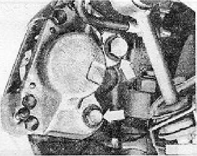
Figure 9.2. Brake shoe mounting bolts (LT 28, 31, 35) (Section 5).
[The article is published on this resource: vwmanual]
On LT 40 and 45 models, the two tie rod end bolts must also be removed.
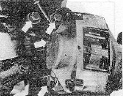
Figure 9.3. Shoe mounting bolts (LT 40, 45) (Section 5).
3. Remove the pad from the disc.
4. Disconnect the flexible brake hose from the brake shoe by turning it no more than a quarter of a turn, and then, holding the hose so as not to twist it, unscrew the shoe from it.
5. Quickly close the hose to prevent fluid loss.
6. Clean off all external dirt and remove the pads as described in Section 3.
7. Remove the dust cap from one piston.
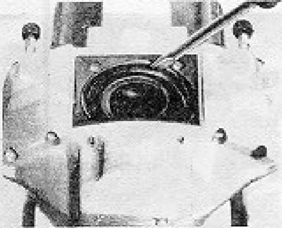
Figure 9.4. Removing the piston dust cap (Section 5).
8. Direct a stream of compressed air to the hole where the hose connects to the shoe and blow the piston out of the cylinder. To do this, you will need a moderate amount of pressure, which can be achieved using a tire pump. Hold the opposite piston with a wire, not with your fingers, otherwise they may get stuck.
9. Using a thin, sharp tool, remove the rubber gasket from the groove in the cylinder, being careful not to damage the cylinder surface.
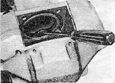
Figure 9.5. Removing the brake shoe piston gasket (Section 5).
10. Inspect the piston and cylinder for signs of damage or metal-to-metal contact and if any are evident, replace the entire pad.
11. If the components are in good condition, purchase a repair kit that will include all the necessary gaskets and other parts that need to be replaced.
12. Install the new piston gasket into the groove, using only your fingers.
13. Apply rubber grease or clean brake fluid to the piston and the inner surface of the cylinder. Insert the piston very straight, but only up to the edge of the piston seals.
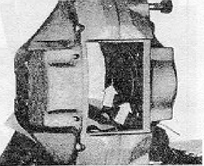
Figure 9.6. Piston and pad alignment (the arrows indicate the recesses of the rim) (Section 5).
14. Now turn the piston so that the recesses on its rim align with the protrusions on the mounting plate. In fact, the mounting plate can be used to determine the correct piston position and then to press the piston into the cylinder and prevent it from rotating during installation. A special tool is provided to rotate the piston after it has been installed.
15. Do not insert the piston fully until the dust cap is installed. Once this is done, insert the piston fully into place.
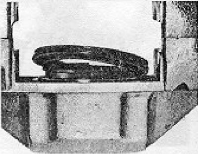
Figure 9.8. Installing the brake shoe piston dust cap.
16. Repeat the above steps for the opposite piston.
17. Connect the flexible hose by screwing the shoe onto its fitting to prevent the piston from twisting.
18. Install the shoe in place, tightening the mounting bolts to the required degree.
19. Reinstall the brake pads.
20. Bleed the hydraulic circuit as described in Section 12.
Visitor comments