



2. To make sure the valve is working, have an assistant press the brake pad and quickly release it. The control valve lever should move.
3. Without a pressure gauge, it is impossible to check and adjust the valve, and the only rough method for assessing its installation is the amount of dust from the friction material of the linings in the rear drums. A small amount of dust indicates that hydraulic pressure is decreasing during braking.
4. If you have a pressure gauge, attach it to the rear wheel cylinder in place of the bleed nipple.
5. Place the vehicle on its wheels on a level surface without load.
Models LT 28 and 31
6. Measure the distance between the bottom of the rear axle shaft and the base of the side body panel. Find this value in the table below and determine the pressure. Now compare the pressure given in the table with the instrument readings, which must be taken with the brake pedal pressed.
Models LT 35, 40 and 45
7. Measure the distance between the centers of the upper and lower shock absorber mounting bolts. Find this measurement in the table below and determine the pressure value that corresponds to your model, now compare this value with the instrument readings that should be taken with the brake pedal pressed.
All models
8. If the measured pressure is too high, reduce the spring tension (i.e. shorten the effective length of the friendship), sliding the bolt within the oblong hole toward the mounting plate (see Figure 9.27).
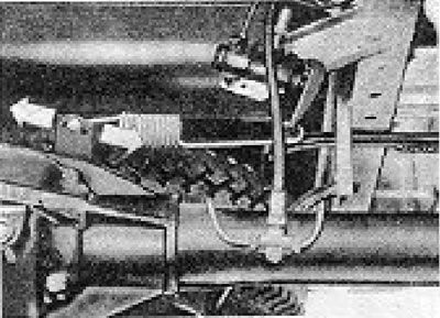
Figure 9.27. Adjusting the brake pressure regulating valve (Section 10).
9. If the pressure value is too low, increase the spring tension. by extending its effective length.
10. Never attempt to adjust the valve while the brake pedal is depressed. After completing the adjustment, check the pressure in the circuit.
| Distance (a), mm | Pressure (bar) | |
| Pickup and Van | High-roof van | |
| 300 to 295 | 7 to 10 | 4 to 7 |
| 295 to 290 | 10 to 12 | 7 to 9 |
| 290 to 285 | 12 to 14 | 9 to 11 |
| 285 to 280 | 14 to 16 | 11 to 13 |
| 280 to 275 | 16 to 18 | 13 to 15 |
| 275 to 270 | 18 to 20 | 15 to 17 |
| 270 to 265 | 20 to 22 | 17 to 19 |
| 265 to 260 | 22 to 24 | 19 to 21 |
| 260 to 255 | 24 to 26 | 21 to 23 |
| 255 to 250 | 26 to 29 | 23 to 26 |
| 250 to 245 | 29 to 32 | 26 to 29 |
| 245 to 240 | 32 to 35 | 29 to 32 |
| 240 to 235 | 35 de 38 | 32 to 35 |
| 235 to 230 | 38 to 41 | 35 to 38 |
| 230 to 225 | 41 to 44 | 38 to 41 |
| Distance (a), mm | Pressure (bar) | ||
| LT 28 and 31 | LT 35 | LT 40 LT 45 | |
| 425 to 420 | 24 to 30 | 27 to 33 | — |
| 420 to 415 | 30 to 35 | 33 to 38 | — |
| 415 to 410 | 35 to 41 | 38 to 44 | — |
| 410 to 405 | 41 to 48 | 44 to 51 | — |
| 405 to 400 | 48 to 55 | 51 to 58 | — |
| 400 to 395 | 55 to 62 | 58 to 66 | 58 to 65 |
| 395 to 390 | 62 to 69 | 66 to 74 | 65 to 72 |
| 390 to 385 | 69 to 77 | 74 to 82 | 72 to 60 |
| 385 to 380 | 77 to 84 | 82 to 91 | 80 to 88 |
| 380 to 375 | 84 to 93 | 91 to 101 | 88 to 97 |
| 375 to 370 | 93 to 101 | 101 to 111 | 97 to 107 |
| 370 to 365 | 101 to 110 | 111 to 120 | 107 to 116 |
| 365 to 360 | 110 to 119 | 120 to 131 | 116 to 128 |
Visitor comments