



Always replace self-locking bolts and nuts.
Check if there are fitted bushings for engine/gearbox alignment in the cylinder block, insert them if necessary.
Without fitted bushings, there are difficulties with shifting, clutch problems and, accordingly, noise in the gearbox (crackling noise in drive wheels).
Make sure the metal gasket is correctly positioned on the engine.
Clean the input shaft splines and apply a thin coat of clutch disc spline grease.
The clutch disc should move easily on the input shaft.
To install the "02S" gearbox, the mounting bracket is equipped with an installation template.
Position the mounting bracket tabs according to the hole positions of the installation template.
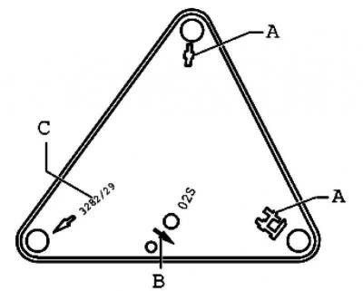
Fig. 3.63. Mounting bracket location
Screw in fastening elements A and C (screws) as shown on the installation template (Fig. 3.63).
Place the gearbox on a tilt stand.
Orient the installation template parallel to the gearbox.
Screw the pin into the hole for the lower powertrain mount mounting screw on the transmission.
Place the tilting device under the vehicle, with the direction of vehicle movement indicated on the installation template.
Raise the gearbox up to the engine itself.
Push the engine forward a little (2nd mechanic).
Align the gearbox with the engine and install it.
Install the lower transmission-to-engine mounting bolts and tighten them securely to the appropriate torque.
(The original article is available on the website vwmanual.ru)
After bolting the gearbox to the engine, disconnect the transmission rack from the gearbox.
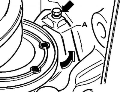
Fig. 3.2. Small shield
Small shield A, if present, install behind the right flange shaft (Fig. 3.2).
Install the upper transmission-to-engine mounting bolts and tighten them securely to the appropriate torque.
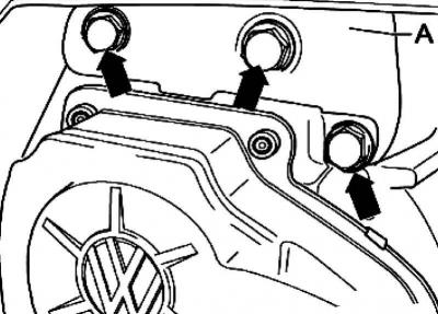
Fig. 3.61. Gearbox console mounting
Install support bracket A onto the gearbox using new hexagon head bolts and tighten them to the appropriate tightening torque (Fig. 3.61).
Adjust the engine/gearbox to the installation position using both lead screws of crosshead A.
Install new left unit support bolts and tighten to specifications.
Caution: Remove the crossmember only when all unit support bolts on the left and right are tightened to the required tightening torque.
Note: Install the engine/gearbox mount without internal stress.
Install the drive shafts on the gearbox.
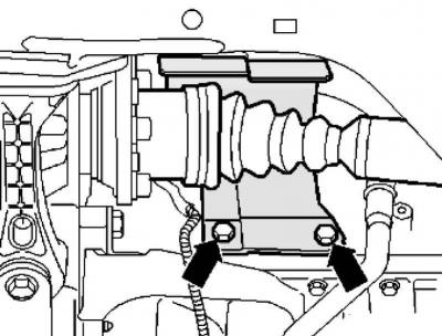
Fig. 3.59. Protective cap for the inner right CV joint
Install the protective cap for the inner right CV joint, if available (Fig. 3.59).
Install the subframe/suspension arm with the swingarm support.
Install the steering gear onto the subframe.
Install the pendulum support on the gearbox.
Assemble the exhaust system and install the exhaust bracket on the subframe.
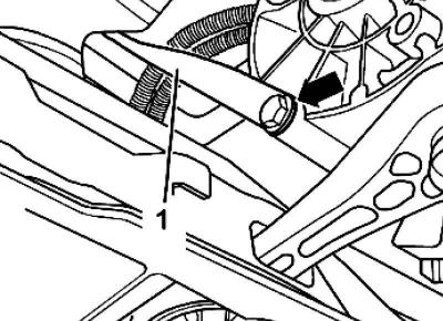
Fig. 3.62. Fastening the exhaust system rod
Install the exhaust system rod 1 onto the gearbox and exhaust system and tighten the bolts to the tightening torque (the mount on the exhaust system is not visible in Figure 3.62).
Install the clutch slave cylinder and tighten the bolts to the specified torque.
Then install the box support A and tighten it securely to the appropriate tightening torque.
Connect connector 1 to the reversing light switch.
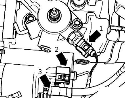
Fig. 3.58. Reversing light switch and starter connectors
Install the starter by connecting connector 2 and screwing on wire 3 (Fig. 3.58).
Attach the ground wire to the upper transmission-to-engine mounting bolt.
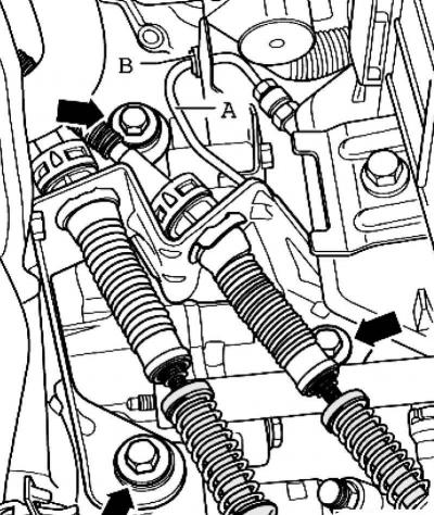
Fig. 3.24. Gearbox bracket and tubular hose
Install bracket B on the gearbox (Fig. 3.24).
Press the hose/pipe line A into the bracket B on the gearbox.
Install the cable stops onto the gearbox and tighten the bolts to the specified torque.
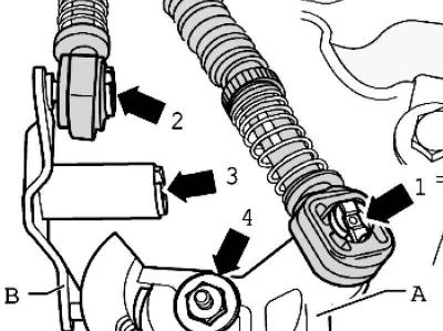
Fig. 3.23. Fastening the clutch cables and gear shift lever
Install gear shift lever A (Fig. 3.23).
Tighten nut 4 to the specified torque.
Install intermediate lever B and secure it with lock washer 3.
Apply a small amount of grease to the shift lever A and idler lever B journals.
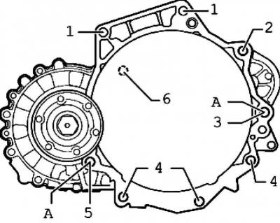
Fig. 3.64. Fastening the gearbox to the engine
Note: Item A Fitted bushings for centering.
Connect the shift cable to gear shift lever 1 and the selector cable to intermediate lever 2.
Visitor comments