



If you want to detect a malfunction in the electrical system or install additional electrical components, then it is impossible to do without an electrical circuit. Guided by the diagram, you can detect the presence of electric current and wire connectors. The corresponding electrical circuit must be closed, otherwise there will be no electric current in it. It is not enough, for example, to supply voltage to the positive terminal of the headlight, if at the same time the electrical circuit is not closed through ground.
Therefore, the battery ground wire is also connected to the car body. However, sometimes this earth connection is not enough, and the corresponding consumer is connected to earth directly by a wire, which is usually painted brown. Switches, relays, fuses, meters, electric motors or other electrical parts can be connected in a separate electrical circuit. To be able to connect these parts correctly, the individual contacts are marked accordingly.
In order to visually order the interlacing of wires, at least on the electrical circuit, the individual current paths are arranged vertically next to each other and numbered.
The vertical lines come up to the mostly grayed out field. This field symbolizes the relay board with fuse holders and, at the same time, the positive connectors of the electrical circuit. First of all, there is also an internal ground wire on the relay board (terminal 31). Thin strokes on the field explain how and which electrical circuits inside the relay board are connected to each other. At the bottom, the electric circuit line is connected to a horizontal line, symbolizing the connection to the car body. The ground connection is usually made directly through the body or through a wire from the ground connector located on the body.
When an electrical circuit ends with a square containing a number, this number indicates the number of the current line to which this electrical circuit is then connected.
It is most reasonable when using an electrical circuit to proceed as follows:
First, they look for the corresponding part on the diagram, for example, a heating fan switch. In the right column next to the part designation in the diagram, the number of the corresponding streamline is indicated, which flows into the horizontal line below.
In order to be able to read an electrical circuit, knowledge of the symbols of many parts is required, in addition, it is necessary to know the most important conventional graphic symbols.
Letter designations of the most important parts:
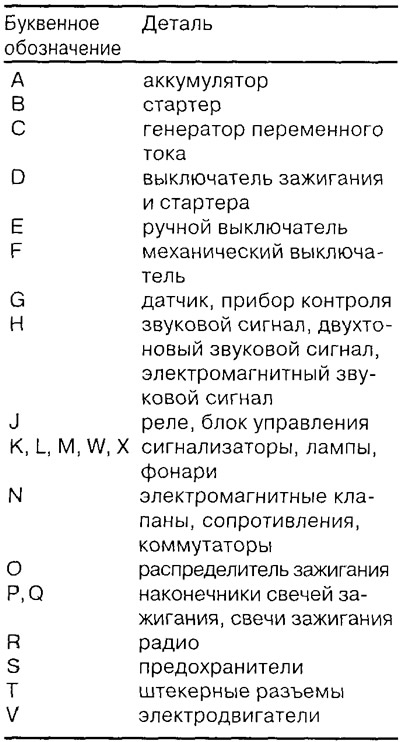
For more accurate recognition, digital symbols are also added to the letter designations.
Relays and electronic control units are usually grayed out. The lines drawn inside them refer to internal wiring. They show how the relay and other electrical/electronic parts are connected both to each other and to the relay board.
The number in the black square indicates the location of the relay on the relay board with fuse holder. Directly at the indicated relay is the designation of the contacts.
Example: If the contacts are labeled 17/87 on the wiring diagram, then 17 is the terminal designation on the relay board and 87 is the terminal designation on the relay/control unit.
The designation of the terminals is given in accordance with the industrial standard of the Federal Republic of Germany (DIN).
The most important terminal designations:
Terminal 30. Battery voltage is always connected to this terminal. The wires are mostly red or red with colored stripes. Terminal 31 is connected to ground. Ground wires are usually brown.
Terminal 15 is powered by the ignition switch. Current flows through the wires only when the ignition is on. The wires are usually green or green with colored stripes.
Terminal X is also energized only when the ignition is on, but the power is interrupted when the starter is turned on. This ensures that the ignition system receives full battery power during the engine start process. All significant current consumers are connected to this electrical circuit. High beam headlights are also supplied with current through this terminal. So when the main beam is on and the ignition is off, the parking lights are automatically switched on.
Construction of electrical circuits
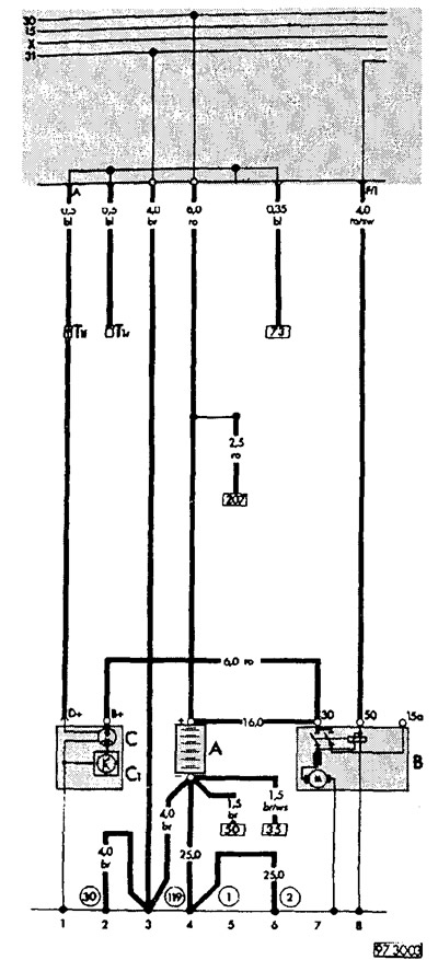
Wiring diagrams VW PASSAT, model 1995
Due to lack of space, every wiring diagram for a particular engine variant or vehicle model, as well as for every model year, cannot be considered. With the new edition, up-to-date wiring diagrams are published as needed, which owners of older models can also refer to.
Attention: Central switchgear/relay location see chapter «Electrical system».
Alternator, battery, starter
Symbols in the wiring diagram on this page.
The relay board with fuse holder is marked with a gray field.
Wire color code:
- ge - yellow
- ws - white
- ro - red
- li - lilac
- bl - blue
- gr - gray
- gn - green
- br - brown
- sw - black
Consumer circuit with wire supply: All switches and contacts are shown at mechanical standstill.
Vehicle weight: Circled numbers indicate installation location (see explanations under the diagram).
Electrical circuit no.: For easy locating (see explanations under the diagram).
Explanations under the diagram
On all electrical diagrams, the same designations are used for the same parts. For example, A is always an accumulator.
A - battery - 4
B - starter - 7-8
C - alternator.. 1-2
C1 - voltage regulator - 1-2
T1f - plug connector, 1-pin, in the engine compartment on the right.. 1
T1r - Male connector, 1-pin, behind the relay board.. 2
Designations in circles
1 - ground jumper, battery - body - 5
2 - jumper mass, gearbox - body - 6
30 - ground connection -1-, next to the relay board - 2
119 - ground connection -2-, in the headlight wiring harness - 4
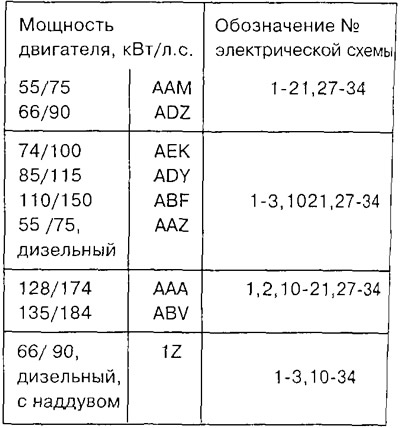
Location of electrical circuits
Visitor comments