



If you want to detect a fault in the electrical system or install additional electrical components, you cannot do without an electrical diagram. Using the diagram, you can detect the presence of electric current and wire connectors. The corresponding electrical circuit must be closed, otherwise there will be no electric current in it. It is not enough, for example, to supply voltage to the positive terminal of the headlight if the electrical circuit is not simultaneously closed through the ground.
Therefore, the battery ground wire is also connected to the car body. However, sometimes this ground connection is not sufficient, and the corresponding consumer is connected to the ground directly by a wire, which is usually painted brown. A switch, relays, fuses, measuring instruments, electric motors or other electrical components can be connected in a separate electrical circuit. In order to be able to connect these components correctly, the individual contacts have corresponding markings.
To visually organize the intertwined wires, at least in the electrical diagram, the individual current lines are arranged vertically next to each other and numbered.
The vertical lines approach the mostly greyed out area at the top. This area symbolizes the relay board with the fuse holders and, at the same time, the positive connectors of the electrical circuit. First of all, the internal ground wire (terminal 31) is also located on the relay board. The fine lines on the field explain how and which electrical circuits inside the relay board are connected to each other. At the bottom, the electrical circuit line connects to the horizontal line, symbolizing the connection to the car body. The connection to the ground is usually made directly through the body or via a wire from the ground connector located on the body.
When an electrical circuit ends with a square containing a number, that number indicates the number of the current line to which this electrical circuit is then connected.
The description below the corresponding electrical circuit names its individual elements. The left column contains an abbreviated designation of the elements, consisting of a letter and a serial number containing from one to three digits. The right column contains the name of the elements.
Letter designations of the most important parts:
| Letter designation | Detail |
| A | battery |
| IN | starter |
| WITH | alternator |
| D | ignition and starter switch |
| E | manual switch |
| F | mechanical switch |
| G | sensor, control device |
| H | sound signal, two-tone sound signal, electromagnetic sound signal |
| J | relay, control unit |
| K,L,M,W,X | signaling devices, lamps, lanterns |
| N | electromagnetic valves, resistors, switches |
| 0 | distributor |
| P.Q | spark plug tips, spark plugs |
| R | radio |
| S | fuses |
| T | plug connectors |
| V | electric motors |
For more accurate recognition, digital symbols are added to the letter symbols.
Relays and electronic control units are usually shown in grey. The lines inside them refer to the internal wiring. They show how the relays and other electrical/electronic components are connected to each other and to the relay board.
The number in the black square indicates the location of the relay on the relay board with the fuse holder. Directly next to the designated relay is the contact designation.
Example: If the contacts on the electrical diagram are marked with the numbers 17/87, then the number 17 is the terminal designation on the relay board, and 87 is the terminal designation on the relay/control unit. The terminal designations are given in accordance with the German industrial standard (DIN).
The most important terminal designations:
Terminal 30. Battery voltage is always applied to this terminal. The wires are mostly red or red with colored stripes.
Terminal 31 connected to ground. Ground connection wires are usually brown.
Terminal 15 is fed through the ignition switch. Current flows through the wires only when the ignition is on. The wires are usually green or green with colored stripes.
Terminal X is also supplied with power only when the ignition is on, but the power supply is interrupted when the starter is engaged. Thanks to this, during the engine starting process, the ignition system receives the full power of the battery. All significant current consumers are connected to this electrical circuit. The high beam headlights are also supplied with current through this terminal. Thus, when the high beam is on and the ignition is off, an automatic switchover to the parking lights occurs.
On the electrical diagram, individual wires are marked with numbers and letter combinations located underneath them.
Example:

The numbers show the cross-section of the wire, and the letters indicate its color. If the letter designation consists of two groups, as in the example, the first group of letters indicates the main color of the wire (ws - white), and the second group - its additional color (ge - yellow). Since it happens that wires of the same color are used in different electrical circuits, it is recommended to control the color combinations of the wires at the corresponding connecting terminals. White wires have an additional number for distinction, which is located under the color designation on the electrical diagram.
Decoding the colors of the wires:
- bl — blue
- br — brown
- ge — yellow
- gn — green
- gr — gray
- li — purple
- or —orange
- ro — red
- sw — black
- ws — white
Wires that are connected to each other via single- or multi-pin plug connectors, along with the letter "T" for the plug connector, have an additional digital combination.
Example: T2p - plug connector, 2-pin; T32/27 - plug connector, 32-pin, with contact point 27.
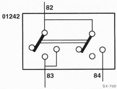
In the electrical diagram, all consumers and switches are shown in a resting state. The changing current flow after the switch is turned on is explained using the example of a two-position switch:
If switch 01242 is pressed into the first position, the current coming from terminal 82 flows through terminal 83. The second jumper also moves one position, but switching on does not occur. Only after pressing the switch into the second position does the second jumper connect the internal wire 82 with wire 84, and now the current continues to flow through wire 84. At the same time, the current supplied when the switch was switched into the first position continues to flow through the internal connection in the switch, namely through the wire coming off at a right angle from wire 83.
Note: Fuses in holders starting from position 23 are designated on electrical diagrams with the number 223.
Electrical diagrams location
VW POLO with steep rear end since November 2002.
Due to space limitations, all electrical diagrams for each model year cannot be considered. However, you can use the suggested electrical diagrams as a guide if your car model is a different year model, since the changes usually only affect a part of the electrical diagrams.
Visitor comments