
Consumer circuit with switching
All switches and contacts are shown in de-energized positions.
«Weight» car
The numbers in the circles indicate where the circuits are connected to the car body.
Electrical circuit number
Applied to make connections easier to find.
Conventions
In all schemes, the same designation is used for each element.
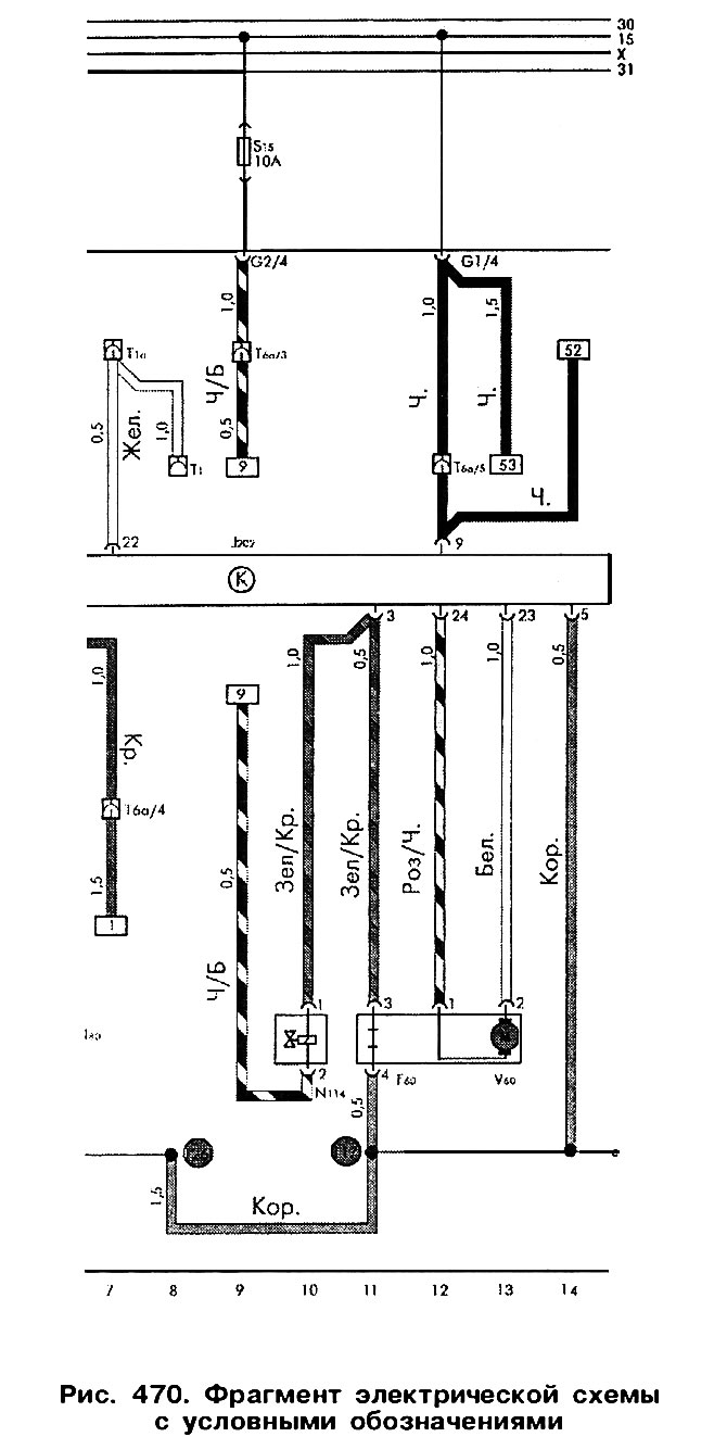
As an example, we give a fragment of one of the electrical circuits (pic. 470), Where:
- F60 - idle switch
- N114 - ignition delay control valve
- T6a - six-pin plug connection
- U60 - idle speed control motor
- 117, 126 - connection points «masses» at the idle switch
In table. 27 provides information on which electrical circuits are used on certain car models, depending on the power of their engines.
Table 27. Location of electrical circuits depending on the model of the car engine
| Engine, power | Designation | Email scheme |
| 1.6/53.55 kW | EZ, RF from 8.89 | 1-17 |
| 1.8/66 kW | GU since 8.89 | 1-17 |
| 1.6/51 kW | PN from 8.89 | 1-2, 5-17 |
| 1.8/66 kW | RP since 8.89 | 18-20 |
| 1.8/82 kW | RV from 8.90 | 21-23 |
The field at the top of the diagram can be «flooded» in gray, it displays the internal layout of the mounting block. Lines with symbols «30», «15», «X», «31» etc. correspond to the terminals of the ignition or instrument switch and starter. The numbers placed in a square frame on a black background and placed next to the control and relay units correspond to the device field number in the mounting block. Wire breaks indicate wire cross section in mm2; the numbers in a square frame at the end of the wire correspond to the number of the route along which the wire is laid.
Connection points with «weight» indicated by numbers in circles: (30), (119).
1. Generator, battery, starter
- A - battery
- B - starter
- C - alternator
- C1 - voltage regulator
- D - ignition switch
- J59 - unloading relay
- E1a - 1-pin battery connector
- 1 - battery jumper - body
- 2 - gearbox jumper - body
- 119 - connection with «weight» -1- in the headlight wiring harness
2. Radiator and heater fans
- E9 - heater fan switch
- F18 - radiator fan thermal switch
- F87 - thermal switch for the servo system for turning off the radiator fan
- J138 Radiator fan servo control unit
- L16 - air flow controller illumination lamp
- No. 23 - heater fan resistance S24 - overheating fuse
- U2 - heater fan
- U7 - radiator fan
- 80 - connection point «masses» -1- in the dashboard wiring harness
- 119 - connection point «masses» -1- in the headlight wiring harness
3. Preheating system, fuel shut-off valve
- F26 - thermal switch
- F35 - preheating thermal switch
- J81 - preheating relay
4. Ignition system
- G40 - Hall sensor
- N - ignition coil
- N41 - control unit TSZ-H
- O - ignition distributor
- P - spark plug connector
- Q - spark plugs
5. Power system, instrument panel
- F1 - oil pressure sensor (1.8 kg/cm2)
- F22 - oil pressure sensor (0.3 kgf/cm2)
- G - fuel gauge sensor
- G2 - coolant temperature sensor
- K1 - high beam warning lamp
- K2 - generator control lamp
- K5 - control lamp of emergency light signaling
- T28 - 28-pin connector on the instrument panel
6. Dashboard
- G1 - fuel gauge
- G3 - coolant temperature gauge
- G5 - tachometer
- J6 - voltage regulator
- J243 - oil pressure sensor
- K3 - oil pressure warning lamp
- L8 - clock illumination lamp
- L10 - instrument panel illumination lamp
- U2 - digital clock
7. Control devices of the brake system
- F9 - parking brake indicator switch
- F34 - brake fluid level indicator switch
- K7 - control lamp of the dual-circuit brake system and parking brake
- 119 - connection with «weight» -1- in the headlight wiring harness
8. Dashboard
- L28 - cigarette lighter backlight
- R - connectors for the radio receiver
- T1v - 1-pin plug connection with mounting block
- T1c - 1-pin plug connection with mounting block
- T2c - 2-pin connector in the engine compartment on the left front
- T2i - 2-pin connector behind the console
- T3a - 3-pin connector behind the console
- T8 - 8-pin connector near the radio
- U1 - cigarette lighter
- W6 - glove box lighting lamp
- 80 - connection point «masses» -1- in dashboard wiring harness
9. Interior lighting
- F2 - front left door limit switch
- F3 - front right door contact
- F10 - rear left door contact
- F11 - rear right door contact
- T1e - 1-pin plug connection in the luggage compartment on the left
- T1q - 1-pin plug connection in luggage compartment, left
- T1f - 1-pin plug connection in luggage compartment, left
- T2e - 1-pin plug connection in the luggage compartment on the left
- W3 - luggage compartment lighting lamp
- W15 - interior lighting lamp
- X - license plate lamp
- 30 - connection point «masses» near the mounting block
- 50 - connection point «masses» in the luggage compartment on the left
10. Headlights, parking lights
- F4 - low beam switch
- L1 - double-filament lamp of the left headlight
- L2 - double-filament lamp of the right headlight
- L13 - high beam headlight bulb
- L14 - lamp high beam right
- M1 - parking light lamp, left
- M3 - parking light lamp, right
- T56 - 5-pin connector behind the cover on the steering column
- 119 - connection point «masses» -1- in the headlight wiring harness
- 120 - connection point «masses» -2- in the headlight wiring harness
11. Direction indicators, emergency light signaling
- E2 - turn signal switch
- E3 - light alarm switch
- E19 - parking light switch
- J2 - alarm relay
- K6 - alarm control lamp
- T4c - 4-pin plug connection behind the cover on the steering column
- T5c - 5-pin connector behind the casing on the steering column
- T7a - 7-pin connector behind the casing on the steering column
12. Direction indicator, brake lights
- М2 - light switching lamp, right
- M4 - lamp switching light left
- M5 - front left direction indicator lamp
- M6 - rear left direction indicator lamp
- M7 - front right direction indicator lamp
- M8 - rear right direction indicator lamp
- M18 - lamp side left direction indicator
- M19 - lamp side right direction indicator
- T1i - 1-pin plug connection
- T2d - 2-pin plug connection
- T6o - 6-pin connector at the left rear light
- T6b - 6-pin connector at the right rear light
- 54 - connection point «masses» in the turn signal harness
- 119 - connection point «masses» in the headlight wiring harness
- 120 - connection point «masses» -2- in the turn signal harness
13. Light switch
- F1 - light switch
- F20 - instrument backlight control
- F - brake light switch
- L9 - light switch illumination lamp
- M9 - stop lamp left
- М10 - stop lamp, right
- T1m - 1-pin plug connection
14. Heated rear window, horn
- C13 - pole connection, in the two-tone horn wiring harness
- E15 - rear window heating switch
- F4 - reversing light switch
- H1 - two-tone sound signal
- J4 - horn enable relay
- K10 - control lamp for turning on the rear window heating
- L39 - rear window heating switch illumination lamp
- M16 - lamp of the left reversing lamp
- M17 - lamp of the right reversing lamp
- Z1 - rear window heater
- 51 - connection point «masses» in the rear window defroster wire harness
- 63, 64 - connection points «masses» in the reversing light harness
- 129 - connection point «masses» in the two-tone horn harness
15. Fog lights
- E23 - switch for fog lights and rear fog lights
- K13 - control lamp for turning on the rear fog lights
- L20 - rear fog lamp
- L40 - Illumination lamp for the fog lamp switch and rear fog lamps
- Z20 - heating resistance of the left nozzle
- Z21 - heating resistance of the right nozzle
- 30 - connection point «masses» beam heating injectors
16. Windshield wiper and washer
- F22 - switch for the time relay of the wiper intervals
- H - sound signal
- J31 - Washer interval time relay
- T4c - 4-pin plug connection behind the casing on the steering column
- T5c - 5-pin connector behind the casing on the steering column
- T7a - 7-pin connector behind the casing on the steering column
- V - wiper motor
11. Windshield washer and rear window wiper (Only for vw Golf 2)
- J30 - rear wiper interval time switch
- V12 - rear wiper motor
- V59 - front and rear washer pump
- 53 - connection point «masses» rear wiper motor
18. Mono-Jetronic injection system control unit with oxygen sensor
- F60 - idle switch
- G39 - oxygen sensor
- J202 - Mono-Jetronic control unit, behind the radiator reservoir on the left
- N80 - canister purge solenoid valve
- N114 - ignition delay control valve
- V60 - idle speed control motor
- 18 - connection point «masses» at the oxygen sensor
- 117, 126 - connection point «masses» at the idle switch
19. Mono-Jetronic injection system, intake manifold heater
- F35 - intake manifold preheating switch
- G42 - intake air temperature sensor
- G62 - coolant temperature sensor
- G69 - throttle valve potentiometer
- J81 - Relay for switching on the heating of the suction pipe
- J202 - Mono-Jetronic control unit behind the radiator reservoir on the left
- N30 - solenoid fuel injector
- N51 - intake manifold heating element
20. Generator, battery, starter
- A - battery
- B - starter
- C - alternator
- C1 - voltage regulator
- D - ignition switch
- J59 - X-contact unloading relay
- 1 - connection point «masses» battery
- 2 - connection point «masses» gearboxes
- 119 - connection point «masses» in the headlight wiring harness
21. Radiator fan
- F18 - coolant fan thermal switch
- G - fuel gauge sender G6 - electric fuel pump G23 - fuel pump
- V7 - engine cooling fan
- 119 - connection point «masses» at the engine cooling fan
22. Injection system «Digifant», ignition and power subsystems
- F60 - idle switch
- F81 - full load switch
- G 19 - air mixture meter potentiometer
- G40 - Hall sensor
- G42 - intake air temperature sensor
- G61 - knock sensor
- G62 - coolant temperature sensor
- J17 - fuel pump enable relay
- J169 - controller for Digifant behind the radiator tank on the left
- N - ignition coil
- N41 - ignition switch TSZ-H
- About - the gauge distributor of ignition
- P - spark plug connector
- Q - spark plugs
23. Fuel injection system «Digifant», elements of the power subsystem
- J169 - controller
- J176 - controller power relay
- G39 - oxygen sensor
- N30-N33 - solenoid fuel injectors
- N71 - idle speed controller
Visitor comments