
The designations of the most important elements are given in Table. 26.
Table 26. Designations of the most important elements
| Designation | Element |
| A | Battery |
| IN | Starter |
| WITH | Alternator |
| D | I Ignition switch |
| E | Manual switch |
| F | Mechanical switch (limit switch, etc.) |
| G | Sensor, control device |
| n | Beep, Dual Tone |
| J | Relay, control unit |
| K, L, M, W, X | Pilot lamps, illuminators |
| N | Solenoid valves, resistors, switching units |
| ABOUT | Distributor |
| P, Q | Spark plug connector, spark plugs |
| R | Radio |
| S | Circuit breakers |
| T | Plug connections |
| V | Electric motors |
To accurately determine the element on the diagram, after the letter of its symbol, the serial number of the element is placed. Relays and electronic control units are depicted, as a rule, with a gray tone.
The number in the black square means the number of the relay field in the mounting block, directly next to the depicted relay is the contact designation.
Example: if the contact on the diagram is marked with the number 17/87, this means that 17 is the terminal number in the mounting block, and 87 is the designation of the relay or control unit terminal.
The most important terminals are marked as follows:
Terminal 30. Battery voltage is constantly applied to this terminal. The wire is always red or red with colored stripes.
Terminal 31 connected to «mass». wires «masses», are usually brown.
Terminal 15 is supplied with voltage through the ignition switch. Voltage is present when the ignition is on. The wires are most often green or green with colored stripes.
The X terminal is also energized when the ignition is on, but the voltage is turned off when the starter is turned on, thereby ensuring that the battery current is fully supplied to the starter. All more or less powerful current consumers are connected to this terminal. As a result, in particular, when the ignition is switched off, the main beam switched on automatically switches to the sidelights.
Symbols of elements and their connections on electrical circuits are given in fig. 469.
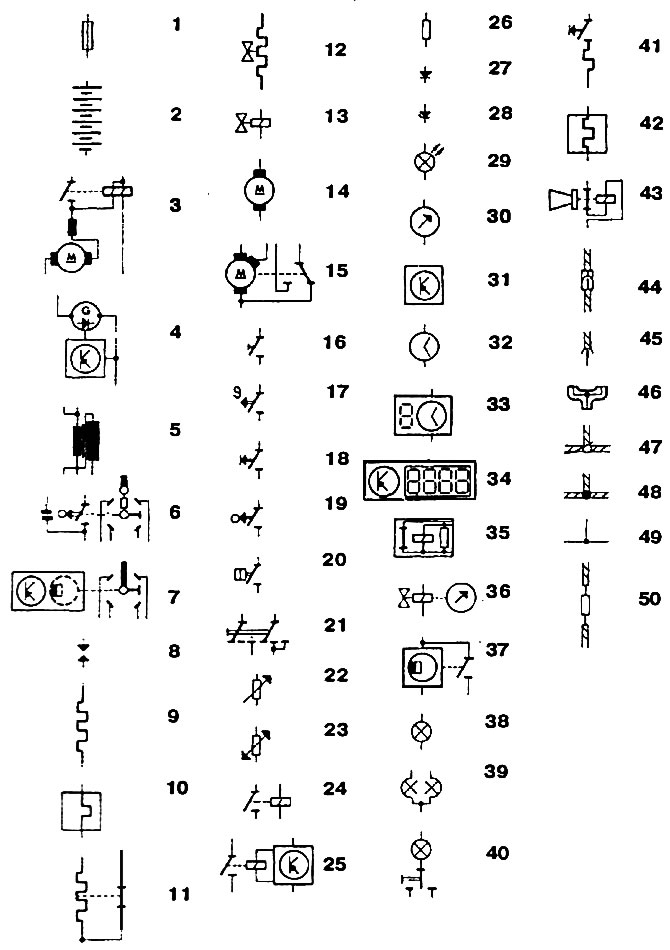
Pic. 469. Symbols of elements and their connection on electrical circuits: 1 - fuse; 2 - battery; 3 - starter; 4 - alternator; 5 - ignition coil; 6 - ignition distributor (mechanical); 7 - ignition distributor (electronic); 8 - tip and spark plug; 9 - starting candle, heating element; 10 - automatic starting device for the carburetor; 11 - thermal time relay; 12 - pressure regulator, additional air damper; 113 - solenoid valve; 14 - electric motor; 115 - wiper motor (2 speed); 16 - switch (manual); 17 - thermal switch; 18 - keyboard; 19 - mechanical switch («trailer»); 20 - pressure switch; 21 - multipole switch (manual); | 22 - variable resistor; 23 - oil and coolant temperature sensor; 24 - relay; 25 - relay with electronic control; 26 - resistor; 27 - diode; 28 - zener diode; 29 - LED; 30 - arrow pointer; 31 - electronic | Control block; 32 - pointer clock; 33 - digital clock; 34 - multifunctional cylinder; 35 - buzzer; 36 - fuel reserve sensor; 37 - tachometer sensor; 38 - incandescent lamp; 39 - incandescent lamp (double strand); 40 - interior lighting lamp; 41 - cigarette lighter; 42 - rear window heater; 43 - sound signal; 44 - multi-pin plug connection: 45 - multi-pin plug connection; 46 - branching connection; 47 - detachable wire connection; 48 - permanent connection of wires; 49 - connection of wires inside the element; 50 - wire with resistance
Visitor comments