
English Русский
Български
Беларускі
Український
Српски
Hrvatski
Română
Polski
Slovenský
Magyar
  |  Articles  |  Sitemap  |  Contacts  |    |
Car maintenance Ford Car maintenance Hyundai Car maintenance Chevrolet Car maintenance BMW Car maintenance Audi Car maintenance Opel Car maintenance AvtoVAZ
VWmanual.ru


Main   Passat   Golf   Polo   Touareg   Tiguan   Sharan   Transporter   Others  
Golf 1 (1974-1984, diesel) Golf 1 (1974-1984, petrol) Golf 2 (1984-1993, petrol) Golf 2 (1984-1993) Golf 3 (1991-1997) Golf 4 (1997-2004) Golf 5 (2003-2008)

Replacing fuses (VW Golf 2)

  • Main
  • Golf
  • Golf 2
  • Electrical equipment
  • Equipment and devices
  • Replacing fuses
            0


To avoid damage to wires and electrical consumers during short circuits and overloads, individual electrical circuits are protected by fuses.

Always disconnect the relevant consumer before replacing a fuse.

Remove the cover from the fuse box. A blown fuse can be identified by a melted metal strip.

Carefully remove the blown fuse from the spring clip (figure 456).
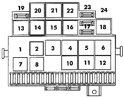
Figure 456. Fuses and relays: 1 - free field; 2 - Inlet manifold preheating relay; 3 - free field;…

Figure 456. Fuses and relays: 1 - free field; 2 - Inlet manifold preheating relay; 3 - free field; 4 - free field; 5 - free field; 6 - two-sound alarm relay; 7 - Fog lights and rear lights relay; 8 - discharge relay; 10 - Rear wiper relay; 12 - light signaling relay; 13 - free field; 14 - free field; 15 - free field; 16 - free field; 17 - Rear fog light fuse (S17j10A); 18 - free field; 20 - free field; 21 - free field; 22 - control device for power off when speed decreases; 23 - free field; 24 - free field


Never "repair" a fuse with tin foil, as this can cause serious damage to another electrical circuit.

It is recommended to always have spare fuses in the car. There are free places for storing them in the bottom of the box with plastic tweezers.


The fuse's rated current is indicated on the back of the fuse. There is also a color code that can be used to determine the fuse's rating (see table 24).

Table 24. Colour coding of fuses


Denomination, AColor code
10red
15blue
20yellow
30green

Insert and snap the fuse box into the instrument panel.

The composition of the fuses depends on the model and year of manufacture of the car. If the consumer is protected by several fuses, then depending on the model it can be protected by one or another fuse. The composition of the fuses is given on the block cover, in the operating instructions and in Table 25.

Table 25. Circuits protected by fuses


№Current strength, AConsumer
110low beam, left side, headlight range control
210low beam, right side, headlight range control
310instrument lighting and license plate lighting
415rear wiper, sunroof control
515windshield wiper and washer
620heater fan, air conditioner
710parking light, starboard side
810parking light, left side
920heated rear window, heated mirror
1015fog lights, rear fog lights
1110high beam, left headlight, high beam indicator lamp
1210high beam, right headlight
1315sound signal, electric radiator fan
1410reversing light, heated washer nozzles, electrically adjustable mirror, heated seats
1510electronic engine management system, carburetor, coolant pump monitoring system
1615instrument panel kit, glove compartment light
1710direction indicators
1820fuel pump, oxygen sensor
1930radiator fan, air conditioner relay
2010stop signal
2115interior lighting, instrument panel kit, radio, clock, central locking, cigarette lighter
2210radio


If necessary, individual harnesses and electrical systems can be disconnected in the vehicle using detachable contact connections (figure 457).
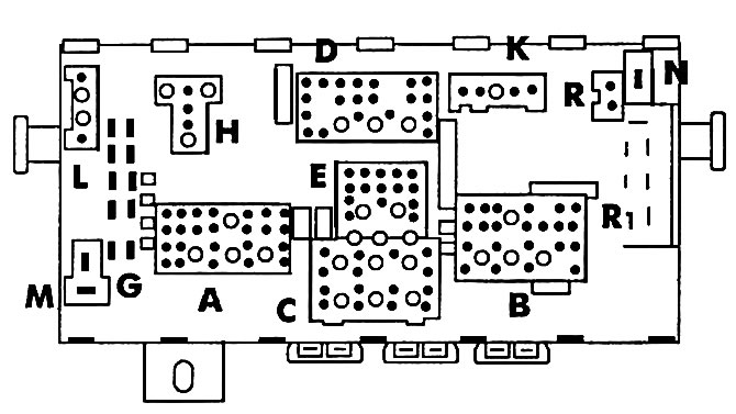
Figure 457. Detachable contact connections:

Figure 457. Detachable contact connections:
A - Multi-pin connector (blue) of the instrument panel cable harness;
B - Multi-pin connector (red) of the instrument panel cable harness;
C - Multi-pin connector (yellow) of the cable harness on the left in the engine compartment;
D - Multi-pin connector (white) of the cable harness on the right in the engine compartment;
E - Multi-pin connector (black) of the rear cable harness on the left in the engine compartment;
G - single-contact plug connection;
H - multi-pin plug connection (brown) air conditioner cable harness;
K - multi-pin plug connection (colorless) cable harness of the safety belt alarm system;
L — Multi-pin plug connection (black), lighting control connector (terminal 56), manual control of the low beam switch and high beam signal (terminal 56b);
N - Single-pin plug connection, socket for isolated fuse (pre-heating plugs or intake manifold pre-heating coil);
R - single-contact plug connection - terminal 30;
A - free

This article is available at russian, bulgarian, belarusian, ukrainian, serbian, croatian, romanian, polish, slovak, hungarian
The text has been checked: Kolesnikov Artem

Share information:

Previous articles
Windscreen wiper — design description
Banners of lamps in headlights
Headlight adjustment
General description of on-board electrical equipment
Next articles
Using Electrical Schematics
Structure of the electrical circuit


Similar articles from other manuals for VW cars:
Replacing fuses Passat B3 (1988-1993)
Replacing fuses Polo 4 (2001-2009)
Fuses Touareg 1 (2002-2006)
Installing hinges after replacing the B-pillar Tiguan 1 (2007-2015)
Checking the engine oil level and replacing it Sharan 1 (1995-2000)
Replacing fuses Transporter T4 (1990-2003)
Replacing fuses Beetle (1960-1986)
Link to this page in different formats


Visitor comments


No comments yet


How much will 31 + 21 =


Golf 5 
  • General information
  • User manual
  • Maintenance
  • Troubleshooting
  • Power unit
  • Engine repair
  • Cooling and ventilation system
  • Fuel system
  • Ignition system
  • Transmission
  • Clutch
  • Mechanical gearbox
  • Automatic gearbox
  • Chassis
  • Brake system
  • Car suspension
  • Steering
  • Body
  • Interior (internal elements)
  • Exterior (external elements)
  • Doors and covers
  • Electrical equipment
  • Power devices
  • Washers and wipers
  • Lighting and appliances
  • Electrical circuits
Golf 4 
  • General information
  • User manual
  • Weekly checks
  • Maintenance
  • Power unit
  • Petrol engines
  • Diesel engines
  • Cooling system
  • Fuel system (petrol)
  • Control system (petrol)
  • Fuel system (diesel)
  • Exhaust system
  • Transmission
  • Clutch
  • Car gearbox
  • Drive shafts
  • Chassis
  • Car suspension
  • Steering
  • Wheels and tires
  • Brake system
  • Body
  • Exterior (external elements)
  • Interior (internal elements)
  • Ventilation and heating
  • Car doors and sunroof
  • Washers and glass cleaners
  • Electrical equipment
  • Power devices
  • Lighting and appliances
  • Electrical circuits
Golf 3 
  • Petrol engine
  • Engine repair
  • Lubrication system
  • Cooling system
  • Ignition system
  • Diesel engine
  • Engine repair
  • Diesel injection system
  • Pre-glow system
  • Transmission
  • Clutch
  • Gearbox and drive shafts
  • Chassis
  • Steering
  • Wheels and suspension
  • Brake system
  • Electrical equipment
  • Lighting and appliances
  • Electrical circuits
Golf 2 
  • General information
  • Introduction to guide
  • User manual
  • Petrol engines 1.3 l
  • Engine repair
  • Lubrication system
  • Cooling system
  • Carburetors
  • Supply system
  • Ignition system
  • Petrol engines 1.6/1.8 l
  • Engine repair
  • Supply system
  • Ignition system
  • Diesel engines
  • Engine repair
  • Lubrication system
  • Cooling system
  • Power and exhaust system
  • Transmission
  • Clutch
  • 4-speed gearbox 084
  • 5-speed gearbox 085
  • 4-speed gearbox 020/4R
  • 5-speed gearbox 020/4T
  • Automatic gearbox
  • Drive shafts
  • Chassis
  • Steering
  • Car suspension
  • Brake system
  • Body
  • Body elements
  • Doors, locks and windows
  • Electrical equipment
  • Equipment and devices
  • Power devices
Golf 2 (petrol) 
  • General information
  • Characteristics
  • Car care
  • Maintenance
  • Power unit
  • Engine repair
  • Engine 1.05/1.30
  • Engine 1.60/1.80
  • Cooling and lubrication system
  • Power and exhaust system
  • Transmission
  • Clutch
  • Car gearbox
  • Drive shafts
  • Chassis
  • Brake system
  • Steering
  • Suspension
  • Body
  • Body and equipment
  • Electrical equipment
  • Lighting and appliances
  • Electrical circuits
Golf 1 (petrol) 
  • General information
  • Characteristics
  • User manual
  • Maintenance
  • Power unit
  • Engine adjustment
  • Engine 1.1/1.3
  • Engine 1.5/1.6/1.8
  • Engine electrical equipment
  • Cooling system
  • Fuel system
  • Transmission
  • Clutch and manual gearbox
  • Automatic gearbox
  • Chassis
  • Steering
  • Front suspension
  • Rear suspension
  • Brake system
  • Electrical equipment
  • Lighting and appliances
  • Electrical circuits
  • Body
  • Body and equipment
  • Optional equipment
Golf 1 (diesel) 
  • General information
  • Specifications
  • Maintenance
  • Power unit
  • Engine repair
  • Exhaust and turbocharger
  • Cooling system
  • Fuel system
  • Fuel injection system
  • Transmission
  • Clutch and drive shafts
  • Car gearbox
  • Chassis
  • Suspension and wheels
  • Steering
  • Brake system
  • Wheels and tires
  • Body
  • Heating and ventilation
  • Exterior (external elements)
  • Interior (internal elements)
  • Doors and windows
  • Electrical equipment
  • Equipment and devices
  • Lighting system
  • Power devices
  • Electrical circuits
VWmanual.ru © 2016-2026 | Mobile version | News and articles | Sitemap: EN BG BY UA RS HR RO PL SK HU | Write message | Site search
Passat B2 • Passat B3 • Passat B4 • Passat B5 • Passat B6 • Golf 1, diesel • Golf 1, petrol • Golf 2, petrol • Golf 2 • Golf 3 • Golf 4 • Golf 5 • Polo 3 • Polo 4 • Touareg 1 • Tiguan 1 • Sharan 1 • Transporter T3 • Transporter T4 • LT 28 • LT 2D • Beetle • Caddy 3 •
Our website uses cookies to ensure functionality and convenience.