



Attention! All switches and contacts are in a mechanically inoperative position.
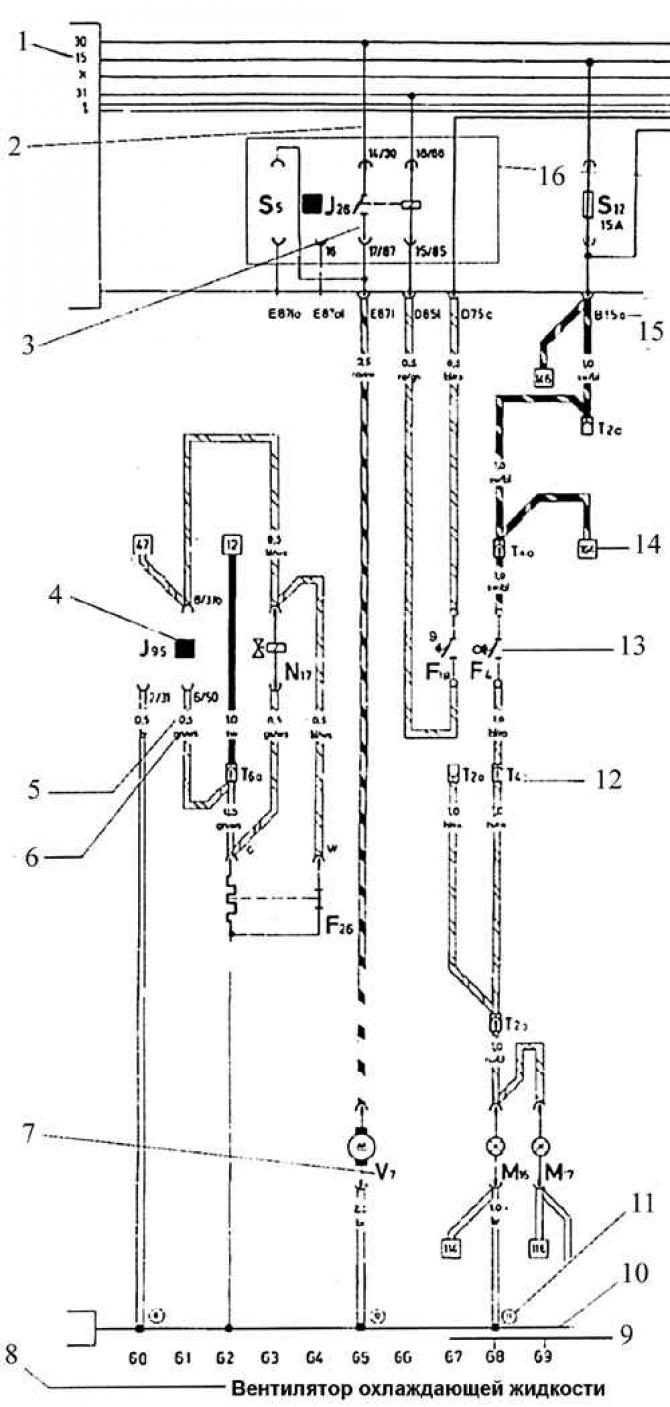
- 1. Terminal designation, 15: When the ignition is on, battery voltage is applied
- 2. Internal connections (fine strokes). These connections are not conductors. However, they conduct current and allow you to trace the direction of current inside the device
- 3. Designation of contacts on the relay/control unit and on the relay board/additional relay board, for example: 17/87 – on the relay board
- 4. Relay location number: indicates the location of the relay on the relay board or additional relay board
- 5. Conductor cross-section, mm²
- 6. The color of the conductor corresponds to the color of the conductor in the car, here: green / white
- 7. Designation of parts: use the legend to find the name of the device conventionally designated on the diagram (here – the cooling liquid fan)
- 8. The designated part, the symbol of which is located in the electrical circuit above 9. The electrical circuit number, to facilitate finding the device in the electrical circuit
- 10. "Mass" of the car (common wire of the power supply system)
- 11. The numbers in the circles indicate the location or arrangement of the connections to the ground
- 12. The combination of letters and numbers designates plug connections, here T4 is a four-pin plug connection. Decoding the designation of the plug connection: T14/12 - means: 14 - pin plug connection, 12 - contact No.12 in the connection
- 13. Schematic symbol: reversing light switch
- 14. The numbers in the squares indicate: a break in the conductor and indicate in which circuit it continues
- 15. Combination of letters and numbers on connections: indicates whether the line is occupied by conductors of multi-contact or individual plug connections, for example B15a – multi-contact connection B, contact 15a.
- 16. Field: Indicates the relay board with fuses
Visitor comments