English Русский
Български
Беларускі
Український
Српски
Hrvatski
Română
Polski
Slovenský
Magyar
  |  Articles  |  Sitemap  |  Contacts  |    |
Car maintenance Ford Car maintenance Hyundai Car maintenance Chevrolet Car maintenance BMW Car maintenance Audi Car maintenance Opel Car maintenance AvtoVAZ
VWmanual.ru


Main   Passat   Golf   Polo   Touareg   Tiguan   Sharan   Transporter   Others  
Golf 1 (1974-1984, diesel) Golf 1 (1974-1984, petrol) Golf 2 (1984-1993, petrol) Golf 2 (1984-1993) Golf 3 (1991-1997) Golf 4 (1997-2004) Golf 5 (2003-2008)

Measuring signals from sensors and other components of the ignition system with an oscilloscope (VW Golf 5)

  • Main
  • Golf
  • Golf 5
  • Power unit
  • Ignition system
  • Measuring signals from sensors and other components of the ignition system with an oscilloscope
            0


Contents: Inductive sensors ↓ Ignition output signal ↓ Primary winding of the ignition coil ↓
When conducting dynamic tests on a running engine, as well as when identifying the causes of periodic failures, an oscilloscope becomes an indispensable tool.

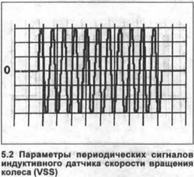
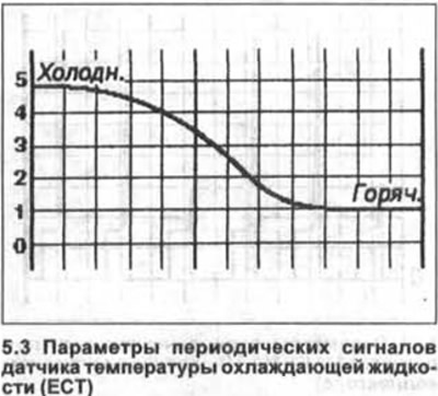
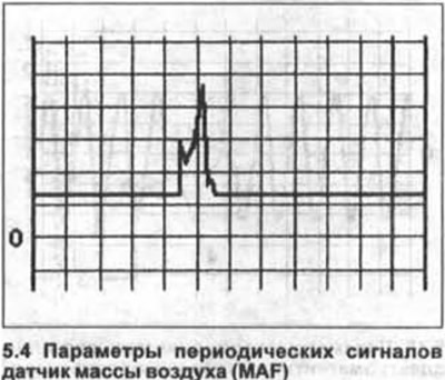
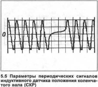
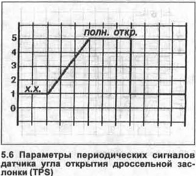
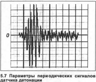
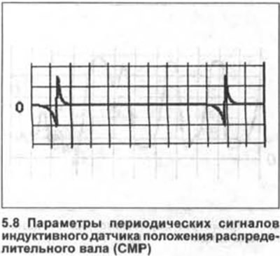
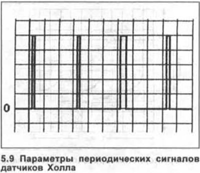
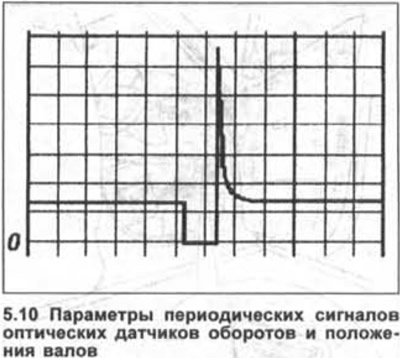
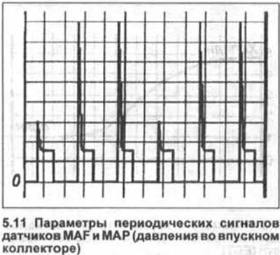
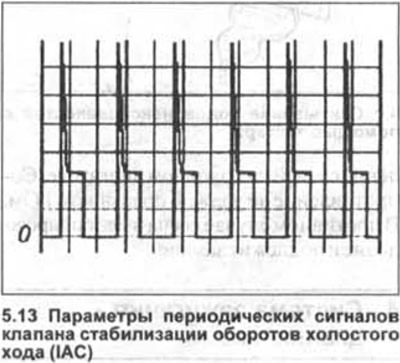
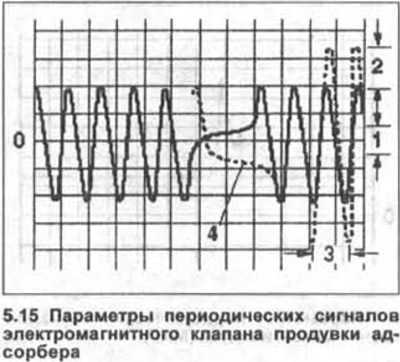
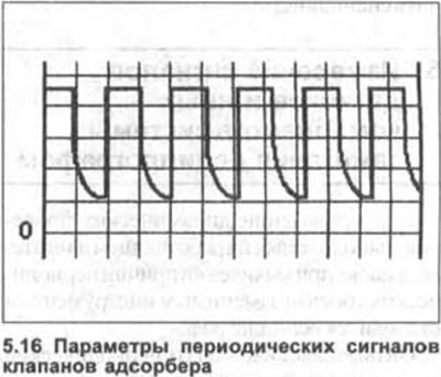
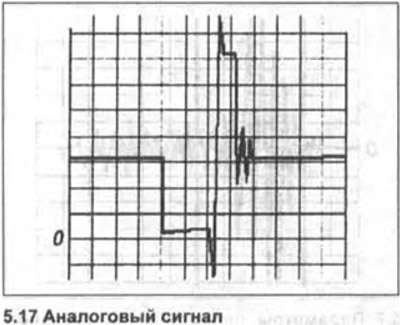
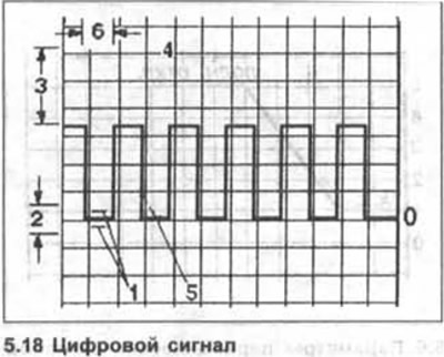
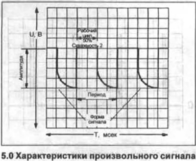
It allows you to observe periodic signals and measure the characteristics of rectangular pulses, as well as slowly changing voltage levels (see illustrations 5.0-5.20).

Modern oscilloscopes are usually equipped with two signal wires with a set of various probes, allowing you to connect the device to almost any device.

The red wire is attached to the positive pole of the oscilloscope and is usually connected to the control unit terminal. The black wire should be connected to a reliable "ground" (-).

The control of the air-fuel mixture composition in modern automotive electronic fuel injection systems is carried out by timely adjustment of the opening duration of the electromagnetic injectors.

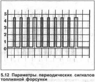
The injector opening period is determined by the duration of the electrical pulses generated by the control unit and supplied to the injectors. The pulse duration usually does not exceed the range of 1+14 ms. A typical oscillogram of a pulse controlling the injector operation is shown in Figure 5.12.

Often, the oscillogram can also show a series of short pulsations that follow immediately after the initiating negative rectangular pulse and maintain the injector in the open state, as well as a sharp positive voltage surge that accompanies the closing of the injector.


The operation of the engine control unit can be easily checked using an oscilloscope by visually observing changes in the shape of the control signal when the engine load changes. Thus, the pulse duration when the engine is idling should be somewhat higher than when running at low speeds. An increase in engine speed should be accompanied by a corresponding increase in the time the injectors remain open.

This dependence is especially evident when opening the throttle valve with short presses on the accelerator pedal.

1. Connect the red wire probe of the oscilloscope to the injector terminal of the control unit.

Securely ground the probe of the second black wire of the oscilloscope.

2. Analyze the waveform read by the oscilloscope when the engine crankshaft rotates.

3. Start the engine and check the control signal shape at idle speed.

4. Increase engine speed to 3000 rpm.

The duration of the control pulses should increase noticeably and then stabilize at a level slightly less than or equal to the idle speed level.

Rapid closing of the throttle valve should result in a straightening of the oscillogram, confirming the closure of the injectors.

When starting a cold engine, it requires some enrichment of the air-fuel mixture, which is achieved by increasing the time the injectors are in the open position.

As the engine warms up, the duration of the control pulses on the oscillogram should continuously decrease, gradually approaching the value typical for idle speed.

In injection systems that do not use a cold start assist device, additional control pulses are used, which appear on the oscillogram as variable-length pulsations.


The table below shows a typical dependence of the duration of the control pulses for opening the injectors on the operating state of the engine.

Engine conditionControl pulse duration, ms
Idle speed1-6
2000-3000 rpm1-6
Full throttle6-35

Inductive sensors


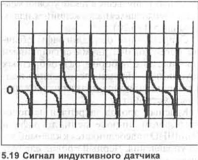
5. Start the engine and compare the oscillogram taken from the output of the inductive sensor with the reference one shown in the illustration.

An increase in engine speed should be accompanied by an increase in the amplitude of the pulse signal generated by the sensor.

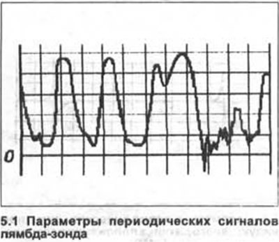
Lambda probe (oxygen sensor)


Attention! The oscillograms shown are typical for the most commonly used zirconium-type lambda probes in cars, which do not use a reference voltage of 0.5 V. Recently, titanium probes have become increasingly popular, the working signal range of which is 0+5 V, with a high voltage level being generated during the combustion of a lean mixture, and a low voltage level during the combustion of a rich mixture.


6. Connect the oscilloscope to the lambda probe terminal on the control unit and to ground (-).

7. Make sure the engine is warmed up to operating temperature.

8. Compare the oscillogram displayed on the meter screen with the reference one shown in the illustration. If the signal being read is not wave-like, but is a line, then, depending on the voltage level, this indicates excessive leanness (0+0.15 V) or over-enrichment (0.6+1 V) of the air-fuel mixture.

If the normal wave signal occurs at engine idle, try pressing the accelerator pedal sharply several times.

Signal fluctuations should not go beyond the range of 0+1 V.

An increase in engine speed should be accompanied by an increase in signal amplitude, and a decrease by a decrease.

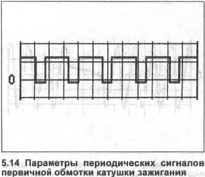
Ignition output signal


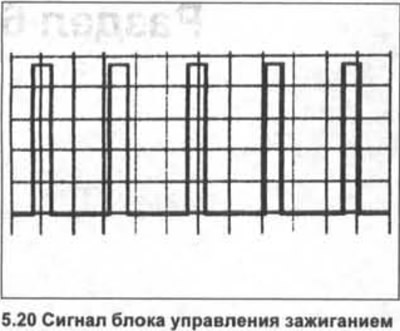
9. Connect the oscilloscope to the ignition unit terminal on the engine control unit and to the ground (-).

10. Warm up the engine to operating temperature and let it idle.

Rectangular DC pulses should appear sequentially on the oscilloscope screen.

Compare the shape of the received signal with the reference one (see illustration).

As the engine speed increases, the signal frequency should increase in direct proportion.

Primary winding of the ignition coil


11. Connect the oscilloscope to the ignition coil terminal and ground (-).

12. Warm up the engine to operating temperature and let it idle.

13. Compare the shape of the received signal with the reference one in the illustration. Positive voltage surges should have a constant amplitude.

Uneven surges can be caused by excessive resistance in the secondary winding, as well as a faulty coil wire.
Uneven surges can be caused by excessive resistance in the secondary winding, as well as a faulty…


Uneven surges can be caused by excessive resistance in the secondary winding, as well as a faulty…


Uneven surges can be caused by excessive resistance in the secondary winding, as well as a faulty…


Uneven surges can be caused by excessive resistance in the secondary winding, as well as a faulty…


Uneven surges can be caused by excessive resistance in the secondary winding, as well as a faulty…


Uneven surges can be caused by excessive resistance in the secondary winding, as well as a faulty…


Uneven surges can be caused by excessive resistance in the secondary winding, as well as a faulty…


Uneven surges can be caused by excessive resistance in the secondary winding, as well as a faulty…


Uneven surges can be caused by excessive resistance in the secondary winding, as well as a faulty…


Uneven surges can be caused by excessive resistance in the secondary winding, as well as a faulty…


Uneven surges can be caused by excessive resistance in the secondary winding, as well as a faulty…


Uneven surges can be caused by excessive resistance in the secondary winding, as well as a faulty…


Uneven surges can be caused by excessive resistance in the secondary winding, as well as a faulty…


Uneven surges can be caused by excessive resistance in the secondary winding, as well as a faulty…


Uneven surges can be caused by excessive resistance in the secondary winding, as well as a faulty…


Uneven surges can be caused by excessive resistance in the secondary winding, as well as a faulty…


Uneven surges can be caused by excessive resistance in the secondary winding, as well as a faulty…


Uneven surges can be caused by excessive resistance in the secondary winding, as well as a faulty…


Uneven surges can be caused by excessive resistance in the secondary winding, as well as a faulty…


Uneven surges can be caused by excessive resistance in the secondary winding, as well as a faulty…


Uneven surges can be caused by excessive resistance in the secondary winding, as well as a faulty…

This article is available at russian, bulgarian, belarusian, ukrainian, serbian, croatian, romanian, polish, slovak, hungarian
The text has been checked: Kolesnikov Artem

Share information:

Previous articles
Ignition system — diagnostics
Glow Plugs — Replacement (Diesel)
Spark plugs and coils (petrol)
General description and safety precautions
Next articles


Similar articles from other manuals for VW cars:
Location of the K-Jetronic fuel injection system and ignition… Passat B4 (1988-1996)
Fuel injection and ignition control system Polo 3 (1995-2003)
Removal and installation of cooling system components (petrol… Touareg 1 (2002-2006)
Removal and installation of cooling system components Tiguan 1 (2007-2015)
General description and operation of the ignition system Sharan 1 (1995-2000)
Ignition system — general information Transporter T4 (1990-2003)
General information on removing and installing fuel system… Caddy 3 (2003-2010)
Link to this page in different formats


Visitor comments


No comments yet


How much will 26 + 36 =


Golf 5 
  • General information
  • User manual
  • Maintenance
  • Troubleshooting
  • Power unit
  • Engine repair
  • Cooling and ventilation system
  • Fuel system
  • Ignition system
  • Transmission
  • Clutch
  • Mechanical gearbox
  • Automatic gearbox
  • Chassis
  • Brake system
  • Car suspension
  • Steering
  • Body
  • Interior (internal elements)
  • Exterior (external elements)
  • Doors and covers
  • Electrical equipment
  • Power devices
  • Washers and wipers
  • Lighting and appliances
  • Electrical circuits
Golf 4 
  • General information
  • User manual
  • Weekly checks
  • Maintenance
  • Power unit
  • Petrol engines
  • Diesel engines
  • Cooling system
  • Fuel system (petrol)
  • Control system (petrol)
  • Fuel system (diesel)
  • Exhaust system
  • Transmission
  • Clutch
  • Car gearbox
  • Drive shafts
  • Chassis
  • Car suspension
  • Steering
  • Wheels and tires
  • Brake system
  • Body
  • Exterior (external elements)
  • Interior (internal elements)
  • Ventilation and heating
  • Car doors and sunroof
  • Washers and glass cleaners
  • Electrical equipment
  • Power devices
  • Lighting and appliances
  • Electrical circuits
Golf 3 
  • Petrol engine
  • Engine repair
  • Lubrication system
  • Cooling system
  • Ignition system
  • Diesel engine
  • Engine repair
  • Diesel injection system
  • Pre-glow system
  • Transmission
  • Clutch
  • Gearbox and drive shafts
  • Chassis
  • Steering
  • Wheels and suspension
  • Brake system
  • Electrical equipment
  • Lighting and appliances
  • Electrical circuits
Golf 2 
  • General information
  • Introduction to guide
  • User manual
  • Petrol engines 1.3 l
  • Engine repair
  • Lubrication system
  • Cooling system
  • Carburetors
  • Supply system
  • Ignition system
  • Petrol engines 1.6/1.8 l
  • Engine repair
  • Supply system
  • Ignition system
  • Diesel engines
  • Engine repair
  • Lubrication system
  • Cooling system
  • Power and exhaust system
  • Transmission
  • Clutch
  • 4-speed gearbox 084
  • 5-speed gearbox 085
  • 4-speed gearbox 020/4R
  • 5-speed gearbox 020/4T
  • Automatic gearbox
  • Drive shafts
  • Chassis
  • Steering
  • Car suspension
  • Brake system
  • Body
  • Body elements
  • Doors, locks and windows
  • Electrical equipment
  • Equipment and devices
  • Power devices
Golf 2 (petrol) 
  • General information
  • Characteristics
  • Car care
  • Maintenance
  • Power unit
  • Engine repair
  • Engine 1.05/1.30
  • Engine 1.60/1.80
  • Cooling and lubrication system
  • Power and exhaust system
  • Transmission
  • Clutch
  • Car gearbox
  • Drive shafts
  • Chassis
  • Brake system
  • Steering
  • Suspension
  • Body
  • Body and equipment
  • Electrical equipment
  • Lighting and appliances
  • Electrical circuits
Golf 1 (petrol) 
  • General information
  • Characteristics
  • User manual
  • Maintenance
  • Power unit
  • Engine adjustment
  • Engine 1.1/1.3
  • Engine 1.5/1.6/1.8
  • Engine electrical equipment
  • Cooling system
  • Fuel system
  • Transmission
  • Clutch and manual gearbox
  • Automatic gearbox
  • Chassis
  • Steering
  • Front suspension
  • Rear suspension
  • Brake system
  • Electrical equipment
  • Lighting and appliances
  • Electrical circuits
  • Body
  • Body and equipment
  • Optional equipment
Golf 1 (diesel) 
  • General information
  • Specifications
  • Maintenance
  • Power unit
  • Engine repair
  • Exhaust and turbocharger
  • Cooling system
  • Fuel system
  • Fuel injection system
  • Transmission
  • Clutch and drive shafts
  • Car gearbox
  • Chassis
  • Suspension and wheels
  • Steering
  • Brake system
  • Wheels and tires
  • Body
  • Heating and ventilation
  • Exterior (external elements)
  • Interior (internal elements)
  • Doors and windows
  • Electrical equipment
  • Equipment and devices
  • Lighting system
  • Power devices
  • Electrical circuits
VWmanual.ru © 2016-2026 | Mobile version | News and articles | Sitemap: EN BG BY UA RS HR RO PL SK HU | Write message | Site search
Passat B2 • Passat B3 • Passat B4 • Passat B5 • Passat B6 • Golf 1, diesel • Golf 1, petrol • Golf 2, petrol • Golf 2 • Golf 3 • Golf 4 • Golf 5 • Polo 3 • Polo 4 • Touareg 1 • Tiguan 1 • Sharan 1 • Transporter T3 • Transporter T4 • LT 28 • LT 2D • Beetle • Caddy 3 •
Our website uses cookies to ensure functionality and convenience.