
Replacing the clutch release bearing
The clutch release bearing with ball bearing is installed in the clutch system. On fig. Shown is a gearbox with a clutch release mechanism on the inside of the gearbox. If this bearing is to be used again, then it is not cleaned with grease-dissolving agents.
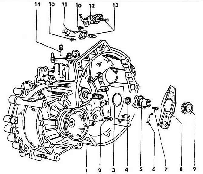
1 - gearbox
2 - pin with ball head
3-O-shaped O-ring
4 - oil-tight ring, clutch shaft
5 - guide sleeve
6 - safety brackets
7 - bolt, tightening torque 25 Nm
8 - clutch release lever
9 - clutch release bearing
10 - bolt, tightening torque 25 Nm
11 - receiving cylinder
12 - mechanical clutch drive
13 - pusher
14 - mounting fingers
When replacing a bearing with a new one, proceed as follows.
Removing the gearbox
«spring out» clutch release bearing brackets (9) from this bearing and pull the bearing.
If the clutch release lever has to be removed (8), then it must be pressed away from the ball head pin (2) with a screwdriver.
Lubricate all bearing surfaces and surfaces in contact with it with graphite grease.
The clutch release bearing is inserted into the 8 clutch release lever and clamped with new brackets.
Install the gearbox.
After installing the gearbox, check the clutch. In doing so, the focus is primarily on «scratching» noise when switching on each individual gear. Noises are heard, first of all, when reverse gear is engaged, if the clutch mechanism does not work.
Hydraulic system
The clutch is hydraulically actuated by the master and slave cylinders. The master cylinder is located on the pedal support (secured with two bolts) and is held on the clutch pedal with one splint finger.
The receiver cylinder is located on the top side of the gearbox and is held in place by bolts.
When removing and installing cylinders, the following instructions must be observed.
Remove the large windscreen cleaning reservoir before removing the master cylinder.
Before removing the receiving cylinder, dismantle the crank arm on the gearbox wall. Do not disconnect the shift cable.
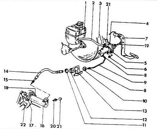
1 - liquid tank
2 - fluid hose
3 - brake booster
4 - mount
5 - master cylinder
6 - nut, tightening torque 7 Nm
7 - clutch pedal
8 - union nut, tightening torque 15 Nm
9 - tube pressure hydraulic line
10, 11 - washers
12 - connector
13 - spring plate
14 - pressure hose
15 - union nut, tightening torque 15 Nm
16 - receiving cylinder
17, 18 - washers, tightening torque 25 Nm
19, 20 - vent plugs
21 - anti-dust protective cover
22 - gearbox
Hydraulic system purge
The purge of the hydraulic system is carried out in the same way as the purge of the brake system, with the difference that the hose is attached to the air valve of the main brake cylinder and the clutch receiver cylinder.
The system should always be purged if the hydraulic lines have been disconnected or if air has entered the system in some other way By moving the clutch pedal down, it is possible to quickly determine if there is pressure in the system. The pedal should move down with constant pressure. Otherwise, the system must be purged.
Visitor comments