
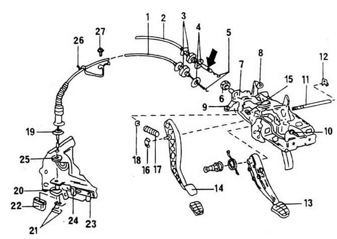
1 - clutch cable (normal execution)
2 - clutch cable with damper (arrow)
3 - rubber stop
4 - washer
5 - support washer
6 - rubber nozzle
7 - accelerator pedal mount (for dismantling, you need to disassemble the steering mechanism)
8, 9 - self-locking nuts, 25 Nm
10 - screws, pedal block mount
11 pedal support bolt
12 - locking clip
13 brake pedal
14 - clutch pedal
15 - thrust clamp
16 - support clamp
17 - return spring
18 - fastening of the withdrawal spring
19 - rubber guide
20 - rubber stop
21 - fastening elements of the clutch cable (normal execution)
22 - counterweight, clutch cable with damper
23 - switch shaft
24 - emphasis
25 - transfer
26 - support
27 - screw
The cable is attached to a support in the engine section on the top side of the crankcase and is provided with an automatic adjustment device near the clutch pedal so no further adjustment is required. The cable is directed vertically down. Before carrying out any work on the trip mechanism, the operating status of the automatic control system can be checked as follows.
Fully depress the clutch pedal at least five times.
In the engine section, align the clutch release lever approximately 10 mm in the direction of the arrow, i.e. in the opposite direction to the normal working stroke.
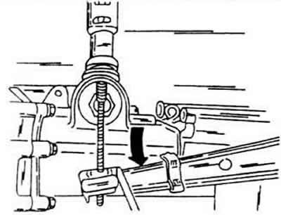
The lever must move freely. If not, the clutch cable needs to be replaced. To guarantee. that the automatic disengaging mechanism is perfectly controlled, it is necessary to depress the clutch pedal five times in succession to ensure that the mechanism operates flawlessly. Otherwise, you need to find out the reason for the failure of the automatic control system.
Visitor comments