
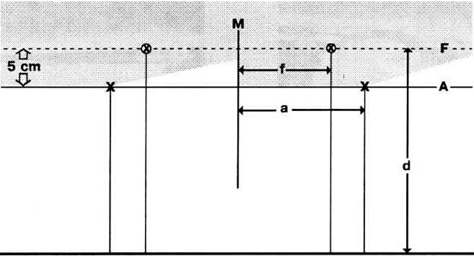
The figure shows the dimensions required to adjust the headlights: d - the height at which the middle points of the headlights are located; F - installation height for an additional high beam headlamp; A - installation height for the main headlight; M - the middle of the car; a is the distance from the headlight to the middle of the car; f is the distance from the middle of the car to the additional high beam headlight.
Place the machine at a right angle at a distance of 5 m from a light wall. Install the new headlight at the same height as the headlight that was not changed. True, lateral adjustment cannot be done in this way.
With the help of a measuring device, an accurate installation is carried out; draw break points on the garage wall (from these points, the light rays rise 15 degrees up-right). For this "Volkswagen" stop at the garage door. Later, with the same position of the machine, you can also check the lateral direction of the light beams.
Draw exact auxiliary lines on the wall; the wall must have at least 9 m of flat surface. These lines are visible in Fig. up. Some more preparatory work is required. You can also glue, for example, crepe tape in appropriate places on the wall (or braid) and draw then.
Auxiliary lines for headlight installation
Stop the machine at a distance of exactly 5 m from the wall, with the front of the machine parallel to the wall.
On both sides, measure the height at which the middle points of the headlights are located; mark on the wall (size "d").
At a distance of 50 mm from this line, draw a line "A" on the wall. This is the inclination of the low beam beam at a distance of 5 m.
Through the rear window, determine the middle of the car by eye; an assistant exactly in the middle should draw a vertical line on the wall "M".
Measure the distance from the middle of the car to the middle point of the dipped beam headlight - size "A"; left and right of the line "M" set aside size "A" and draw on the cross.
These crosses should be used to adjust the breakpoints of the low beam.
Only for a car with auxiliary high beam headlights: points at a height "d" and on the line "F" join together.
If there are additional high beam headlights, then in size "f" between the center of the vehicle and the center point of the headlight to the right and left of "M" on line "F" draw crosses.
On these crosses it is necessary to adjust the beams of the high beam headlights.
The location of the set screws is shown in the illustrations.
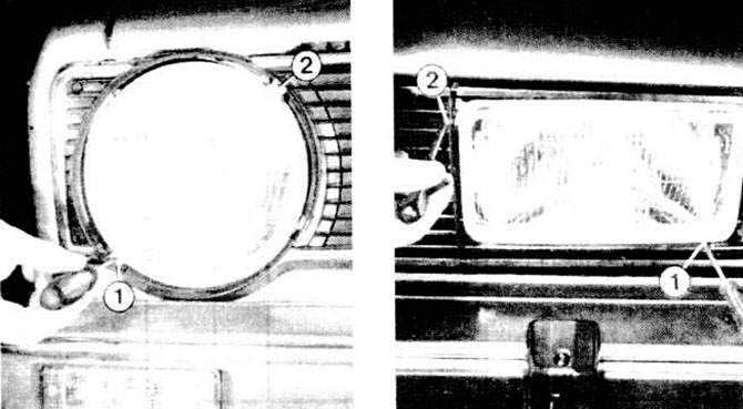
The illustrations show the headlight mounting screws: left - in the model "Golf", on the right - in the model "Jetta": 1 - height setting; 2 - side installation.
Visitor comments