



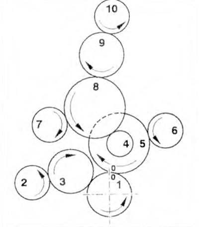
Figure 4.29. Drive gears: 1 - Crankshaft gear; 2 - Power steering vane pump gear; 3, 4, 5, 8, 9 - Intermediate gears; 6 - Cooling system pump gear; 7 - Fuel pump gear; 10 - Camshaft gear.
1. Check the axial clearance of gears 3, 4, 5 and 8 (figure 4.30) Axial clearance: 0.06-0.12 mm
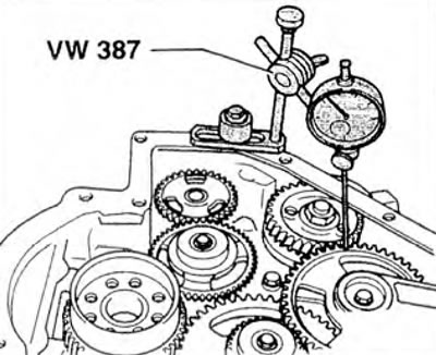
Figure 4.30. Checking the axial clearance of gears 3, 4, 5 and 8.
2. Check the axial clearance of the intermediate gear 9 of the camshaft drive (figure 4.31). Axial clearance: 0.06-0.12 mm.
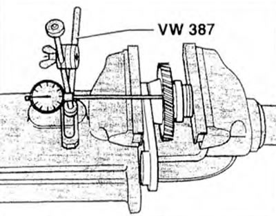
Figure 4.31. Checking the axial clearance of intermediate gear 9 of the camshaft drive.
3. To adjust the clearance, use adjusting washers, which have three thicknesses. They are installed between the thrust washer and the gear.
| Adjusting washers | Thickness, mm |
| Washer 1 | 2.45-2.49 |
| Washer 2 | 2.50-2.54 |
| Puck 3 | 2.56-2.60 |
Checking the free play of gears 9 and 10
4. Remove the cylinder head cover.
5. Before removing the camshaft gear, align the TDC marks (arrow) (figure 4.17).
6. Remove the camshaft gear and install a dial indicator on the cylinder head (figure 4.32). Measure the free play of gear 9. Free play of gear: 0.06-0.17 mm.
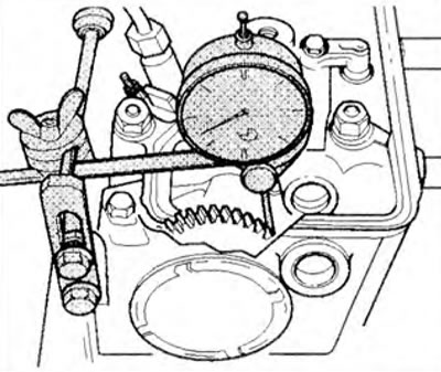
Figure 4.32. Install a dial indicator on the cylinder head and measure the free play of gear 9.
7. Install the camshaft gear and tighten its mounting bolt by hand.
8. Now determine the free play by simultaneously holding the intermediate shaft and rotating the camshaft (figure 4.33).
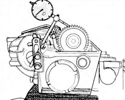
Figure 4.33. Determine the free play by simultaneously holding the intermediate shaft and rotating the camshaft.
9. If the specified value is not achieved, unscrew the intermediate shaft cover. Loosen the adjuster bearing mounting bolt (arrow A), but do not remove it (figure 4.34). Free play can be adjusted by moving the bearing from side to side (arrows).
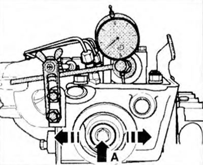
Figure 4.34. Loosen the adjusting bearing mounting bolt (arrow A), but do not remove it. Free play can be adjusted by moving the bearing from side to side (arrows).
10. After adjustment, tighten the adjusting bearing bolt to 65 Nm.
11. Install the intermediate shaft cover with a new oil seal.
12. Lock the camshaft from rotating, install the locking device 3445 on the cams of the 4th cylinder (figure 4.28).
13. Remove locking device 3445.
14. Install the cover on the crankshaft damper.
15. Install key 3447 on the central bolt of the damper and, holding the crankshaft from rotating, tighten the camshaft gear mounting bolt to 180 Nm
16. Remove key 3447.
17. Tighten the cover mounting bolts on the crankshaft damper to 10 Nm.
18. Install the cylinder head cover.
Visitor comments