



Contents: Examination ↓ Installation ↓
The cylinder head is shown in the figure 4.15.
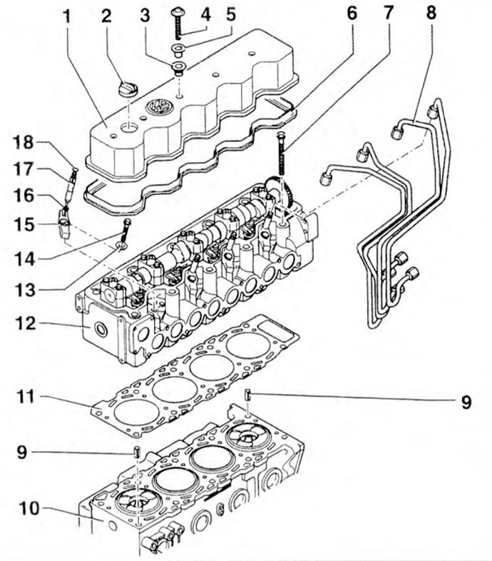
Figure 4.15. Cylinder head: 1 - Cylinder head cover; 2 - Lid; 3, 19 - Oil seals; 4, 7, 9, 11, 17 - Bolts; 5 - Bushing; 6, 14 - Gaskets; 8 - High pressure fuel lines; 10 - Bracket; 12 - Guide bushings; 13 - Cylinder block; 15 - Cylinder head; 16 - Washer; 18 - Retainer; 20 - Nozzle; 21 - Rubber bushing.
Examination
1. Check the cylinder head for deformation (figure 4.16). Permissible deformation: 0.1 mm. If the deformation is greater than the permissible limit, the cylinder head must be reground.
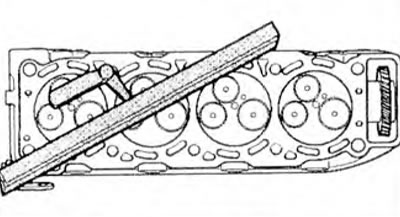
Figure 4.16. Checking the cylinder head deformation.
The order of loosening the cylinder head mounting bolts is shown in the figure 4.17.
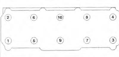
Figure 4.17. Procedure for loosening the cylinder head mounting bolts.
Installation
2. Before installing the cylinder head, align the TDC marks on the crankshaft pulley and the casing (arrow) (figure 4.18).
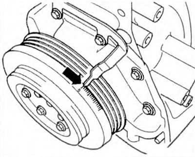
Figure 4.18. Before installing the cylinder head, align the TDC marks on the crankshaft pulley and the housing (arrow).
3. Install the camshaft so that the piston of the 1st cylinder is at TDC (figure 4.19).
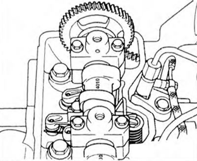
Figure 4.19. Install the camshaft so that the piston of the 1st cylinder is at TDC.
4. Lock the camshaft with locking tool 3445 (figure 4.20). Install the cylinder head gasket in the required position.
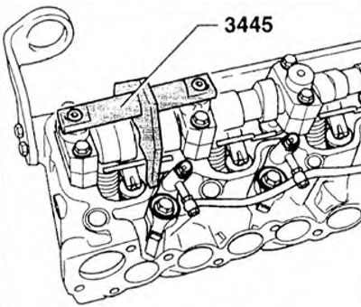
Figure 4.20. Lock the camshaft with locking tool 3445.
(The original article is available at: VWMANUAL)
5. Install the cylinder head, insert 10 cylinder head mounting bolts and tighten the cylinder head mounting screws as shown in the figure 4.21. Tightening is carried out in 5 stages:
- 1st stage - 30 Nm,
- 2nd stage - 60 Nm,
- Stage 3 - 100 Nm,
- 4th stage - 1/4 turn (90°),
- 5th stage - 1/4 turn (90°).
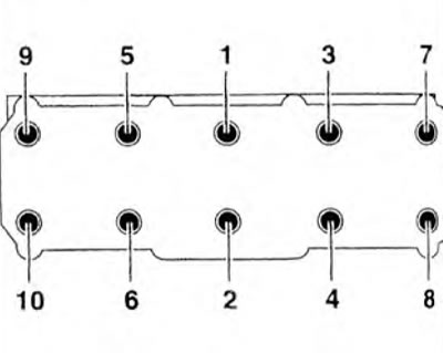
Figure 4.21. Cylinder head bolt tightening sequence.
Visitor comments