



Fuel tank
The fuel tank is shown in figure 3.40 in Section 11 of Chapter 3.
Fuel pump
The fuel pump is shown in the figure 4.41.
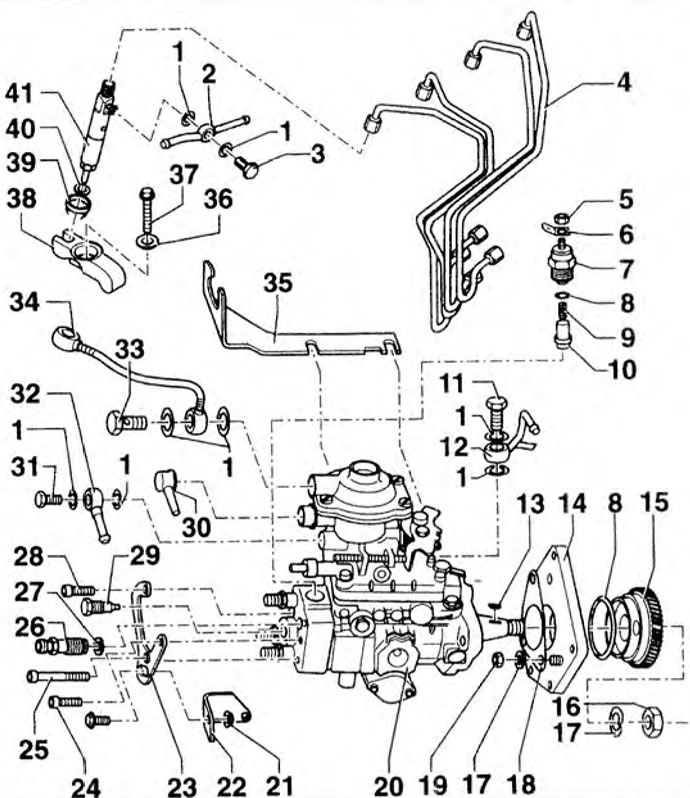
Figure 4.41. Fuel pump: 1, 8, 29 - Sealing rings; 2, 28, 34 - Adapters; 3, 5, 13, 14, 26, 27, 29, 30, 31, 33, 35, 38 - Bolts; 4 - Fuel lines; 6, 19, 22, 24 - Nuts; 7 - Wire eye; 10 - Spring; 11 - Thrust piece; 12, 25 - Brackets; 15 - Fuel injection line; 16 - Key; 17 - Support flange; 18 - Fuel pump gear; 20 - Engraver; 21 - Gasket; 23 - Fuel pump; 32 - Rubber support; 36 - Vacuum tube; 37 - Washer (until 12.97.); 39 - Mounting plate; 40 - Rubber bushing; 41 - Heat-protective gasket; 42 - Injector.
Removal
1. Disconnect the fuel lines from the fuel pump.
2. Remove the cylinder head cover.
3. Turn the crankshaft by placing the key on the central bolt of the damper.
4. Remove the plug from the hole in the flywheel housing.
5. Rotate the crankshaft until mark 1 on the flywheel aligns with the mark on the intermediate flange (arrow) (figure 4.26). In this position, the TDC mark on the damper should be aligned with the mark on the casing (arrow) (figure 4.17).
6. Rotate the crankshaft in the direction of rotation so that it is set to a position of 25° after TDC (figure 4.42).
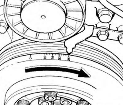
Figure 4.42. Rotate the crankshaft in the direction of rotation so that it is set to the 25° after TDC position.
7. Disconnect the wiring connector from the fuel shut-off valve and unhook the fuel control cable from the fuel pump.
8. Unscrew the mounting bolts of both fuel pump brackets (arrows) (figure 4.43). Unscrew the three bolts 1 securing the pump housing.
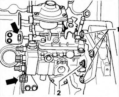
Figure 4.43. Loosen the bolts securing both fuel pump brackets (arrows). Loosen the three bolts 1 securing the pump housing.
9. Remove the pump.
Installation
10. Check the crankshaft installation at 25° after TDC (figure 4.42).
11. Unscrew nuts 3 (figure 4.44). Set the fuel pump to the middle position and hand tighten the intermediate flange mounting bolts to the pump. Place the mark on the fuel pump (arrow) between the connection of the 1st and 4th cylinders 2.
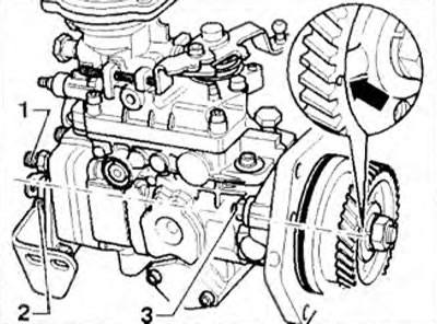
Figure 4.44. Unscrew nuts 3. Set the fuel pump to the middle position and hand tighten the bolts securing the intermediate flange to the pump. Place the mark on the fuel pump (arrow) between the connection of the 1st and 4th cylinders 2.
12. Rotate the fuel pump using the pulley in the direction of the 1st cylinder until resistance is felt.
13. Install the fuel pump into the inspection hole with a new sealing ring, holding it parallel to the support bolt holes.
14. Tighten the housing mounting bolts 1 by hand (figure 4.43).
15. Check the start of fuel injection. If the injection start point cannot be set to the specified value, it is necessary to reset the fuel pump by moving the gear position by one tooth.
16. Tighten nuts 2 to 20 Nm, bolts 1 and support bolts (arrow) for mounting the brackets to 20 Nm (figure 4.43).
17. Fill the fuel tank with clean diesel fuel through the fuel drain line, connect all fuel lines and wiring connectors.
Visitor comments