
English Русский
Български
Беларускі
Український
Српски
Hrvatski
Română
Polski
Slovenský
Magyar
  |  Articles  |  Sitemap  |  Contacts  |    |
Car maintenance Ford Car maintenance Hyundai Car maintenance Chevrolet Car maintenance BMW Car maintenance Audi Car maintenance Opel Car maintenance AvtoVAZ
VWmanual.ru


Main   Passat   Golf   Polo   Touareg   Tiguan   Sharan   Transporter   Others  
LT 28 (1975-1991) LT 2D (1996-2003) Beetle (1960-1986) Caddy 3 (2003-2010)

Turbocharger with attached elements (VW Lt 2d)

  • Main
  • Volkswagen
  • LT 2D
  • Power unit
  • Diesel engines 2.8 l
  • Turbocharger with attached elements
            0


Contents: Removal ↓ Installation ↓ Examination ↓
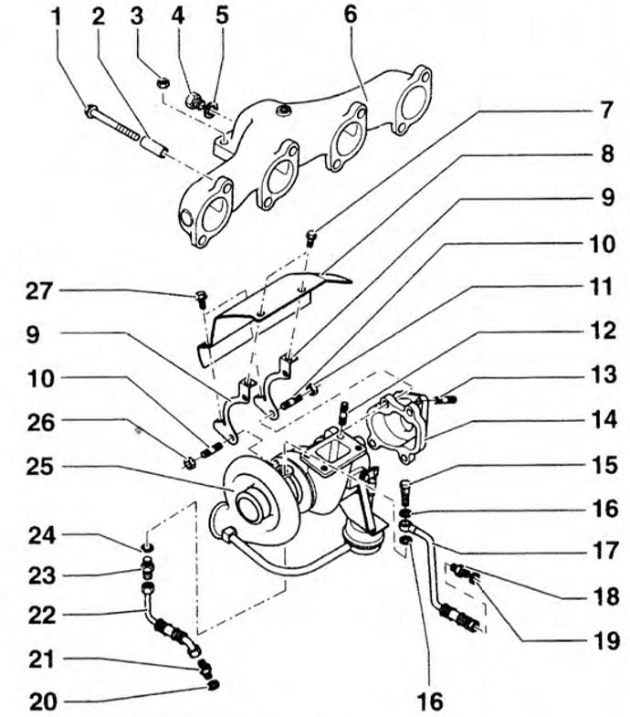
The turbocharger with its components attached is shown in the figure 4.46a, intercooler - in Figure 4.46b.

Figure 4.46a. Turbocharger with attached components: 1, 4, 7, 15, 27 - Bolts; 2 - Bushing; 3, 5,…

Figure 4.46a. Turbocharger with attached components: 1, 4, 7, 15, 27 - Bolts; 2 - Bushing; 3, 5, 11, 26 - Nuts; 5, 16, 19, 20, 24 - Oil seals; 6 - Exhaust manifold; 8 - Heat-protective casing; 9 - Retainer; 10, 12, 13 - Hairpins; 14 - Lid; 17 - Oil pressure line; 18, 21, 23 - Adapters; 22 - Oil drain line; 25 - Turbocharger.
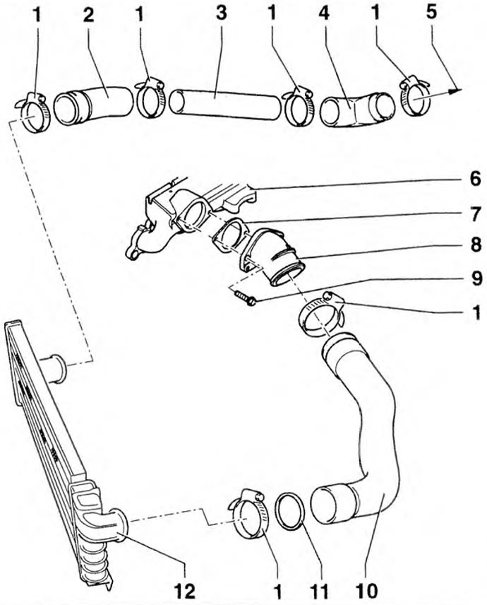

Figure 4.46b. Intercooler: 1 - Clamps; 2, 4, 10 - Discharge pipes; 3 - Boost air supply pipe; 5 -…

Figure 4.46b. Intercooler: 1 - Clamps; 2, 4, 10 - Discharge pipes; 3 - Boost air supply pipe; 5 - To the turbocharger; 6 - Intake manifold; 7 - Gasket; 8 - Adapter: 9 - Bolt; 11 - Sealing ring;12 - Radiator.


Removal


1. Disconnect the negative cable from the battery.

2. Loosen the mounting bolts (arrows) and remove the heat shield 1 (figure 4.47).
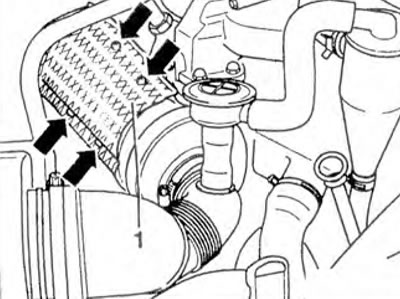
Figure 4.47. Loosen the mounting bolts (arrows) and remove the heat shield 1.

Figure 4.47. Loosen the mounting bolts (arrows) and remove the heat shield 1.


3. Disconnect the clamps 1 and remove the tubes (arrows) from the oil separator (figure 4.5). Remove the tubes as an assembly.

4. Disconnect the discharge pipe (arrow) from the turbocharger (figure 4.48).
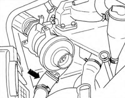
Figure 4.48. Disconnect the discharge pipe (arrow) from the turbocharger.

Figure 4.48. Disconnect the discharge pipe (arrow) from the turbocharger.


5. Disconnect the pressure 1 and drain 2 oil lines from the turbocharger (figure 4.49).

6. Remove the front part of the exhaust pipe, unscrew the nuts securing the turbocharger to the exhaust manifold.

7. Remove the turbocharger.


Installation


8. Installation is carried out in the reverse order of removal.

Examination


The turbocharger and the boost pressure control valve form one unit. If the fault occurs with the turbochargers, the entire unit must be replaced. Repairs are not permitted.

Boost pressure is measured at full load either on the road or on a dyno. The test lasts approximately 10 seconds.
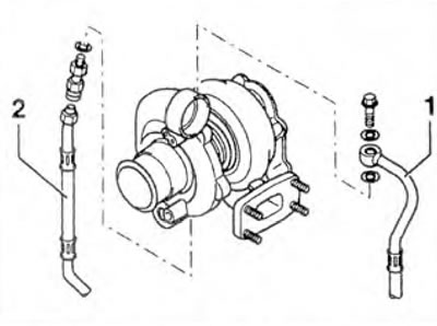
Figure 4.49. Disconnect the pressure 1 and drain 2 oil lines from the turbocharger.

Figure 4.49. Disconnect the pressure 1 and drain 2 oil lines from the turbocharger.


9. Disconnect the test tube (black) between the boost pressure limiting valve and the compressor outlet.

10. Attach the additional tube to the compressor and connect the test tube to the T-piece.

11. Connect the VAG 1397 A/1 tube to the VAG 1397 A tester with a T-piece (figure 4.50).
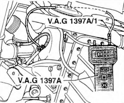
Figure 4.50. Connect the VAG 1397 A/1 tube to the VAG 1397 A tester with a T-piece.

Figure 4.50. Connect the VAG 1397 A/1 tube to the VAG 1397 A tester with a T-piece.


12. Turn on measurement level II.

13. Measure the boost pressure with the throttle fully depressed: on the test bench - in 3rd (for manual transmission) or 2nd (automatic transmission) gear at 3500 rpm, and on the road - in 2nd (for manual transmission) or 1st (automatic transmission) gear at 40 km/h. At 2000-3000 rpm, press the "M" button on the tester and read the measured value. It should be 0.90-1.00 bar.

14. If the value does not match the required value, replace the turbocharger.

15. If the boost pressure is too high and the wastegate valve is not locked, loose or leaking, replace the turbocharger again.

This article is available at russian, bulgarian, belarusian, ukrainian, serbian, croatian, romanian, polish, slovak, hungarian
The text has been checked: Kolesnikov Artem

Share information:

Previous articles
Checking and adjusting the fuel injection start point
Fuel pump
Cooling system
Checking the oil pressure and oil pressure sensor
Lubrication system
Pistons and connecting rods
Next articles
Exhaust gas system


Similar articles from other manuals for VW cars:
Turbocharger Passat B3 (1988-1993)
Codes (designations) of elements of electrical connection… Golf 1 (1974-1984, petrol)
Removal and installation windshield wiper elements Polo 3 (1995-2003)
Checking the turbocharger Touareg 1 (2002-2006)
Turbocharger with add-on elements Tiguan 1 (2007-2015)
Diesel engine fuel system and turbocharger Sharan 1 (1995-2000)
Designation of elements in electrical circuits Transporter T4 (1990-2003)
Link to this page in different formats


Visitor comments


No comments yet


How much will 50 + 13 =


Caddy 3 
  • General information
  • User manual
  • Daily care
  • Maintenance
  • Petrol engines 1.4 l
  • Engine repair
  • Cooling and lubrication system
  • Power and exhaust system
  • Petrol engines 1.6 l
  • Engine repair
  • Cooling and lubrication system
  • Power and exhaust system
  • Diesel engines
  • Engine repair
  • Cooling and lubrication system
  • Power and exhaust system
  • Transmission
  • Mechanical gearbox 0AH
  • Mechanical gearbox 0A4
  • Drive shafts
  • Chassis
  • Car suspension
  • Steering
  • Brake system
  • Body and wiring diagrams
  • Interior and exterior
  • Electrical circuits
Beetle 
  • General information
  • Maintenance
  • Power unit
  • Engine repair
  • Cooling and lubrication system
  • Supply system
  • Exhaust system
  • Transmission
  • Clutch
  • Car gearbox
  • Chassis
  • Front suspension
  • Rear suspension
  • Steering
  • Brake system
  • Wheels and tires
  • Body
  • Exterior
  • Electrical equipment
  • Equipment and devices
  • Power devices
  • Electrical circuits
LT 2D 
  • General information
  • User manual
  • Maintenance
  • Power unit
  • Petrol engines 2.3 l
  • Diesel engines 2.5 l
  • Diesel engines 2.8 l
  • Injection system (diesel 2.8 l)
  • Transmission
  • Clutch
  • Manual gearbox
  • Differential
  • Chassis
  • Car suspension
  • Steering system
  • Brake system
  • Body
  • Body elements
  • Heating system
  • Electrical equipment
  • Equipment and devices
  • Electrical circuits
LT 28 
  • General information
  • Maintenance
  • Power unit
  • Petrol engines 2.0L
  • Petrol engines 2.4L
  • Diesel engines
  • Cooling and heating
  • Fuel and exhaust system
  • Ignition system
  • Transmission
  • Clutch
  • Car gearbox
  • Cardan shaft
  • Rear axle
  • Chassis
  • Brake system
  • Car suspension
  • Steering system
  • Body
  • Body elements
  • Doors, locks and windows
  • Electrical equipment
  • Power devices
  • Equipment and devices
  • Electrical circuits
VWmanual.ru © 2016-2026 | Mobile version | News and articles | Sitemap: EN BG BY UA RS HR RO PL SK HU | Write message | Site search
Passat B2 • Passat B3 • Passat B4 • Passat B5 • Passat B6 • Golf 1, diesel • Golf 1, petrol • Golf 2, petrol • Golf 2 • Golf 3 • Golf 4 • Golf 5 • Polo 3 • Polo 4 • Touareg 1 • Tiguan 1 • Sharan 1 • Transporter T3 • Transporter T4 • LT 28 • LT 2D • Beetle • Caddy 3 •
Our website uses cookies to ensure functionality and convenience.