



2. Disconnect the fuel supply lines.
3. Remove the cover on the damper.
4. Rotate the crankshaft until mark 1 on the flywheel aligns with the mark on the intermediate flange (arrow) (figure 4.26).
5. Unscrew the plugs in the flywheel housing and in the fuel pump head.
6. Screw in the adapter and digital indicator (measurement range 0-5.0 mm) into the hole for the plug in the fuel pump head with a preload of 1.0 mm (figure 4.45).
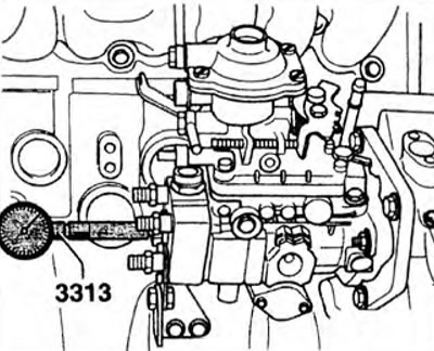
Figure 4.45. Screw in the adapter and digital indicator (measurement range 0-5.0 mm) into the hole for the plug in the fuel pump head with a pre-tension of 1.0 mm.
7. Slowly rotate the crankshaft in the direction opposite to its direction of rotation (counterclockwise) until the TDC mark on the flywheel aligns with the mark on the intermediate flange (arrow) (figure 4.26).
Determine the starting point of fuel injection: test value 1.70-1.80 mm; adjustment value - 1.74±0.4 mm.
8. To adjust, loosen the nuts of the 2 bolts securing the rear support of the fuel pump (arrow) (Fig. 4.43).
9. Set the fuel injection start point and rotate the fuel pump.
10. Tighten nuts 2 to 20 Nm, bolts 1 and support bolts (arrow bracket fastenings to 20 Nm (figure 4.43).
11. Remove the digital indicator and screw the plug into the fuel pump head to 20 Nm.
12. Remove the key and install the damper cover.
13. Install the fuel injection lines.
14. Install the cylinder head cover.
Visitor comments