



Brake caliper FS-II/FS-III
Note: The front wheels of the car use calipers of different designs. Therefore, using the drawings, you should first find out what design of calipers are installed on your car.
Removal
Please note: Brake pads are subject to the operating permit and are intended by the manufacturer for the corresponding vehicle model. Therefore, it is recommended to use only brake pads approved for use by the vehicle manufacturer.
Mark the direction of rotation of the tires with an arrow. Loosen the wheel bolts. Raise the front of the car onto jack stands and remove the wheels.
Attention: Strictly follow the instructions given in the chapter "Removal and installation a wheel".
Safety instructions
There is a risk of accident when lifting the vehicle! Please read the section "Lifting the vehicle" beforehand.
Note: If the brake pads are to be reinstalled, their location must be marked before removal. Swapping the pads, for example, swapping the outer pad with the inner pad or moving the pad from the right wheel to the left wheel and vice versa, is not allowed. It is necessary to replace all front brake pads at the same time, even if only one of them has reached the wear limit.
[The article is posted on the portal: VWmanual.ru]
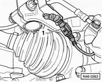
For vehicles with a brake pad wear sensor, disconnect plug connector "1".
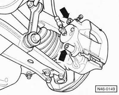
Remove the protective "arrow" caps from both guide pins.
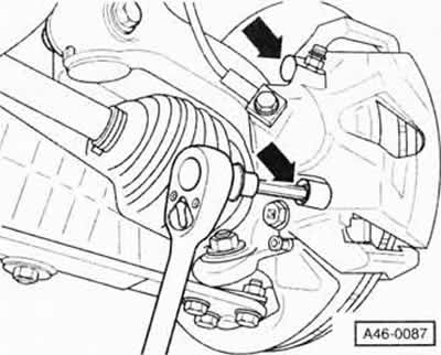
Remove both guide pins from the brake caliper.
Remove the brake caliper and hang it on a wire from the body. Note: The brake caliper should not just hang down; the brake hose must not be twisted or stretched.
Remove both brake pads.
Installation
Caution: When the brake pads are removed, do not press the brake pedal, otherwise the piston will be pushed out of the caliper housing. In this case, the caliper assembly must be removed and the piston inserted at a service station.
Before installing the pads, examine the brake discs by touch with your fingers to check for dents. Discs with dents can be turned down (at a service station) if they are then thick enough. Be sure to turn both discs of the bridge to the same size.
Measure the thickness of the brake discs, see the relevant chapter below.
Caution: Use only alcohol to clean the brakes. Degrease the guide surfaces and the pad areas in the housing shaft with a rag soaked in alcohol. Do not use solutions containing mineral oils or tools with sharp edges. Pay special attention to removing any possible adhesive residue from the mating surfaces of the outer brake pads.
Check the brake cylinder piston seal for cracks. Replace a damaged seal immediately, as penetrating dirt will quickly damage the caliper seal. In this case, the caliper must be disassembled (at a service station).
Note: If the brake pads are very worn, check the ease of movement of the brake cylinder piston. To do this, insert a wooden block into the brake caliper and ask an assistant to slowly press the brake pedal. The piston in the cylinder should be easily pressed out and pressed back in. When checking, the other brake pad, as well as the opposite brake caliper, must be installed in their places. If the piston moves heavily, repair the brake caliper (at a service station).
Note: When the piston is pressed into the cylinder, the brake fluid from the brake cylinder is squeezed into the expansion tank. Monitor the fluid level in the tank and, if necessary, suck out excess fluid with a siphon.
Safety instructions
For suction, use a bottle that was used to remove air from the hydraulic system, or a plastic bottle that has previously only come into contact with brake fluid. Do not use bottles intended for drinking liquids! Brake fluid is poisonous and should never be sucked out by mouth through a hose. Use a siphon for suction. After replacing the brake pads, the brake fluid level in the expansion tank should also not be higher than the MAX mark, since the liquid expands when heated. Brake fluid leaking from the tank gets under the master brake cylinder and destroys the paintwork, which leads to corrosion.
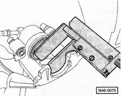
Press the brake cylinder piston into the cylinder using the return device. Note: You can also use a hardwood rod for pressing (with a hammer handle), however, special attention must be paid to ensuring that the piston is not skewed and that the piston surfaces and dust seal are not damaged.
Insert the brake pads into the caliper body and connect them to the piston.
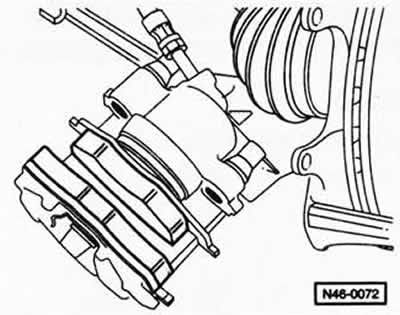
Brake caliper FS-II:insert brake pads. The brake pad with an increased lining area is located on the outside.
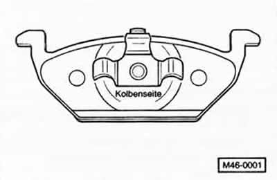
Brake caliper FS-II/FS-III:insert the brake pads into the caliper housing. The brake pad has the inscription on the back -Kolbenseite- (piston side) is inserted into the piston.
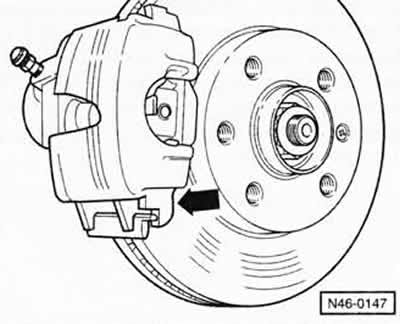
Brake caliper FS-II/FS-III:mount the caliper housing with the brake pads on the steering knuckle. First, place the caliper housing from below "arrow". Screw the caliper housing to the pad guide with two guide pins and tighten them to a torque of 30 Nm.
Insert the guide pin protective caps.
If equipped, connect and secure the brake pad wear sensor plug.
Ensure the previous direction of rotation of the tires, tighten the wheels with bolts, lower the car and only then tighten the wheel bolts in a crosswise manner with a torque of 120 Nm.
Attention: Strictly follow the instructions given in the chapter "Removal and installation a wheel".
Caution: Press the brake pedal firmly several times with the vehicle stationary until you feel strong resistance. This will center the brake pads and position them according to the operating conditions.
Check the brake fluid level in the expansion tank and, if necessary, top up the tank with fluid up to the MAX mark.
Carefully work in new brake pads by repeatedly braking the car from 80 km/h to 40 km/h by lightly pressing the brake pedal. Allow the brakes to cool between braking operations.
Caution: New brake pads must be run in. Avoid unnecessary braking until the vehicle has covered approximately 200 km.
Note: In some areas, worn brake pads must be treated as special waste. Local authorities will advise whether they can be disposed of via industrial waste collection points similar to household waste.
Attention, perform a safety compliance check:
- Are the brake hoses tightly tightened?
- Is the brake hose in the holder?
- Are the air bleed valves tightened?
- Is there enough fluid in the brake system?
- With the engine running, perform a leak test. To do this, apply a force of 200 to 300 N to the brake pedal for approximately 10 seconds (from 20 to 30 kg). Do not loosen the brake pedal. Check all connections for leaks.
C54-II/POLO brake caliper only
Note: The design of the C54-II brake mechanism is fundamentally the same as the Lucas brake mechanism for the IBIZA.
Attention: Observe safety precautions, see above for contents of this chapter.
Removal
For vehicles with a brake pad wear sensor, disconnect the sensor plug.
Unscrew the upper and lower hex bolts from the caliper body, remove the caliper body and hang it on a wire to the body.
Caution: The brake caliper should not just hang down; the brake hose must not be twisted or stretched.
Remove the heat shield from the caliper housing.
Remove the inner brake shoe from the shoe guide.
Pull the outer brake shoe out of the retaining spring and remove it forward from the shoe guide.
Remove the upper and lower retaining springs from the shoe guide.
Installation
Insert a new heat shield into the piston.
Insert new brake shoe retaining springs.
Tighten the new bolts securing the brake caliper to the brake shoe guide to a torque of 30 Nm.
Connect the plug connector of the brake pad wear sensor.
Visitor comments