



Lucas brake caliper
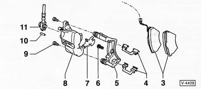
3 - brake pads
4 - retaining springs for brake shoes
5 - brake shoe guide
6 - ribbed head bolt, 125 Nm
7 - heat shield
8 — brake caliper housing
9 - Hexagon head bolt, 30 Nm
10 - unloading pin
11 - brake hose
With ring nipple and hollow bolt, 35 Nm.
Note: There are different brake caliper designs. Therefore, you should first find out which design of caliper is installed on your vehicle using the illustrations. This chapter only describes the differences from the FS-II/FS-III disc brakes. All installation and safety instructions are the same for the Lucas brake.
Removal
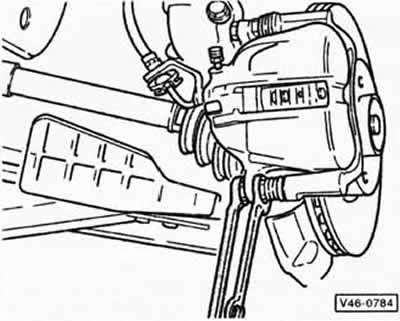
Using an open-end wrench to hold the guide pin, remove the lower bolt "9" securing the caliper housing, see Figure V-4429.
Tilt the caliper body upward.
For vehicles with a brake pad wear sensor, disconnect the sensor plug, see instructions for the caliper fS-II brakes.
Remove the brake pads from the housing and remove the heat shield from the piston.
Remove the brake shoe retaining springs.
Installation
Insert the heat shield into the piston so that the brake pads fit into the bore of the caliper body.
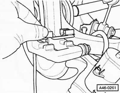
Insert new brake shoe retaining springs.
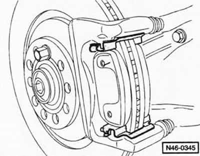
Insert the brake pads. Make sure that the brake pads are located within the retaining surfaces.
Tilt the brake caliper downwards. Hold the guide pin with an open-end wrench and tighten the new self-locking bolt "9" securing the caliper housing to 30 Nm, see Figure V-4429.
If equipped, connect the brake pad wear sensor plug and secure it to the shock absorber strut bracket.
Follow all other installation instructions, see instructions for the support fS-II brakes.
Visitor comments