



Contents: Removal ↓ Installation ↓
Note: The following illustrations show the replacement of the left headlight adjustment servo motor.
Note: Replacing the right headlight servomotor is done in a similar manner.
Removal
Remove the headlight.
Remove cap 3.

Fig. 7.63. Servo drive housing
Unscrew the fastening bolt 2 and completely remove the housing 1 (Fig. 7.63).
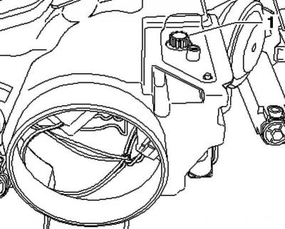
Fig. 7.64. Gear
Remove gear 1 from its mounting hole upwards (Fig. 7.64).
Note: When removing the gear, be careful not to lose the small O-ring.
Disconnect plug connection 2.
Unlock the headlight range control servomotor 1 in direction B.
carefully press the servo motor ball head A back out of its guide.
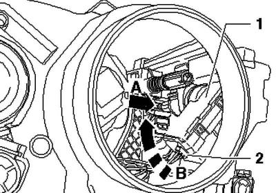
Fig. 7.65. Headlight corrector servomotor
Remove servomotor 1 from its mount upwards (Fig. 7.65).
Installation
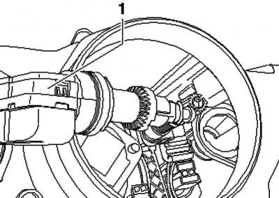
Fig. 7.66. Installing the headlight corrector servomotor into the mount
Fully insert the headlight corrector servomotor 1 in the unlocked position into its mount (Fig. 7.66).
Lock the headlight corrector servomotor 1 by turning it all the way in direction B (Fig. 7.65).
Carefully push the ball head of servo motor A back first.
Finally, carefully insert the servo motor ball head in direction into mount 1 (Fig. 7.65).
Note: When doing this, move the reflector back slightly to make it easier for the ball head to engage into the mount.
Reconnect connector 2 of the headlight range control servo motor.
Insert gear 1 into its mounting hole (Fig. 7.64).
Install housing 1, securing it with bolt 2, and put on casing 3 (Fig. 7.63).
Note: When installing, pay attention to the tight fixation of the cap. If water gets inside the headlight, the headlight may be damaged.
Visitor comments