
English Русский
Български
Беларускі
Український
Српски
Hrvatski
Română
Polski
Slovenský
Magyar
  |  Articles  |  Sitemap  |  Contacts  |    |
Car maintenance Ford Car maintenance Hyundai Car maintenance Chevrolet Car maintenance BMW Car maintenance Audi Car maintenance Opel Car maintenance AvtoVAZ
VWmanual.ru


Main   Passat   Golf   Polo   Touareg   Tiguan   Sharan   Transporter   Others  
Golf 1 (1974-1984, diesel) Golf 1 (1974-1984, petrol) Golf 2 (1984-1993, petrol) Golf 2 (1984-1993) Golf 3 (1991-1997) Golf 4 (1997-2004) Golf 5 (2003-2008)

Removal and installation switches (VW Golf 4)

  • Main
  • Golf
  • Golf 4
  • Electrical equipment
  • Lighting and appliances
  • Removal and installation switches
            0


Contents: Light switch ↓ Headlight range control/instrument…↓ Window switches ↓ Mirror control switch ↓ Sunroof/Interior Light Control Switch ↓ Hazard warning light switches, rear…↓ Fuel filler cap lock switch ↓
Warning: When the battery is disconnected, the contents of the memory cells, such as the radio code, are erased. Without the code, the radio can only be reconnected by the manufacturer.


Warning: Before removing any switch, remove the ground cable from the battery and reconnect it to the battery only after the switch is installed.


Light switch


1. Set the light switch control knob to position 0.
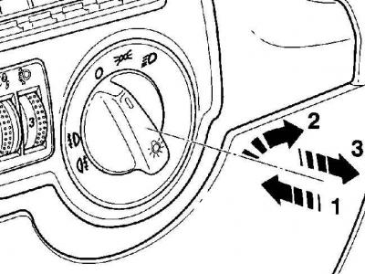
1. Set the light switch control knob to position 0.


2. Press the light switch handle (arrow 1). In this position, turn it clockwise (arrow 2) and remove the light switch from the instrument panel (arrow 3).

3. Disconnect the electrical connector from the switch.

4. Connect the electrical connector to the light switch.
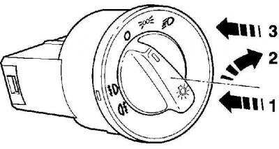
4. Connect the electrical connector to the light switch.


5. Insert the light switch into the instrument panel socket, then press it (arrow 1) and simultaneously turn it clockwise (arrow 2). This will lower both hooks of the switch.


6. Press the light switch handle (arrow 3) until the switch is firmly fixed in the instrument panel.

Headlight range control/instrument panel light intensity control


Warning: To avoid scratching the instrument panel when removing the switch, tape the area around the switch.
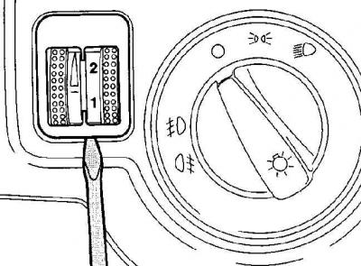

Warning: To avoid scratching the instrument panel when removing the switch, tape the area around…


1. Using a thin screwdriver blade, pry the switch housing out of the instrument panel.

2. When installing the switch, press it into the instrument panel until it locks firmly into place.

Window switches


The window lift switches on the driver's door are made as a block. If there is a fault, the entire block must be replaced.

Driver's door

1. Using a thin screwdriver blade, slide the interior door handle trim toward the door.

2. Remove the door handle together with the control unit from the interior door trim.

3. Disconnect the electrical connector.
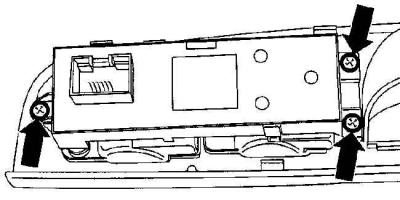
3. Disconnect the electrical connector.


4. Unscrew the three screws and remove the control unit.


5. Installation is carried out in the reverse order of removal.

Front passenger door/rear doors

6. Remove the interior door trim.

7. Disconnect the electrical connector from the window switch.
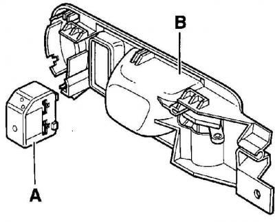
7. Disconnect the electrical connector from the window switch.


8. Press the side surface of the switch (A) and remove it from the socket in the housing (B) of the inner door opening handle.

9. Insert the window switch into the socket of the inner door handle housing until it clicks into place.

10. Further installation is carried out in the reverse order of removal.

Mirror control switch


1. Remove the door trim.

2. Disconnect the electrical connector from the switch.
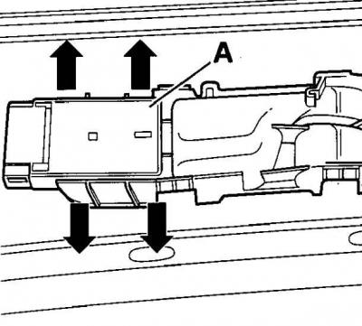
2. Disconnect the electrical connector from the switch.


3. Press the side fasteners of the switch (A) outward and remove it from the housing.

4. Insert the switch into the housing and secure it.

5. Further installation is carried out in the reverse order of removal.

Sunroof/Interior Light Control Switch


Sunroof/Interior Light Control Switch
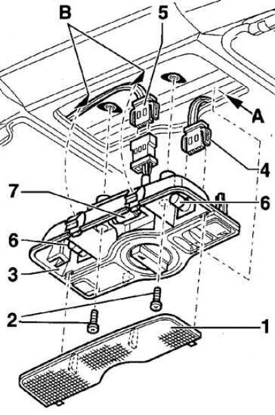


Sunroof/Interior Light Control Switch

  • 1 - diffuser;
  • 2 - screws;
  • 3 - switch housing;
  • 4 - electrical connector;
  • 5 - electrical connector;
  • 6 - light bulb;
  • 7 - lampshade bulb;
  • A - direction of removal;
  • B - hooks

1. Remove the diffuser. To do this, insert a knife blade or other similar object into the gap between the housing and the diffuser and carefully pry the diffuser out.

2. Remove the screws securing the switch.

3. Press the switch in the direction of the arrow (A) and remove its rear part from the hooks (B).

4. Disconnect the electrical connectors and remove the switch.

5. Installation is carried out in the reverse order of removal.

Hazard warning light switches, rear window defrosters and more


1. The switches are mounted in the same way.

2. To avoid scratching the instrument panel when removing the switch, tape the area around the switch.
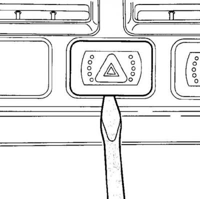
2. To avoid scratching the instrument panel when removing the switch, tape the area around the…


3. Using a thin screwdriver blade inserted under the switch, remove the switch from the instrument panel socket.

Warning: The switch consists of a switch housing and a switch with a function symbol. The switch snaps into the switch housing. If only the switch has been removed from the instrument panel, use pliers to remove the switch housing from the instrument panel.


4. Disconnect the electrical connector from the switch.

5. When installing the switch, connect the electrical connector to it and secure it with the clamp.

6. Slide the switch into the instrument panel socket until it locks into place.

Fuel filler cap lock switch
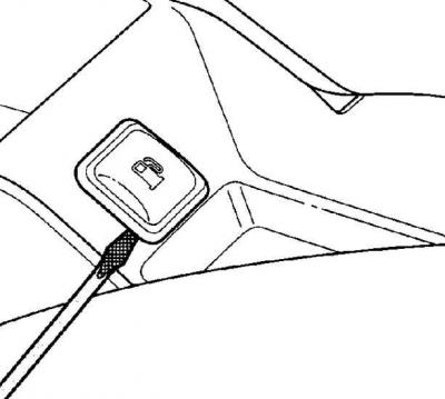


Fuel filler cap lock switch


1. Insert a thin screwdriver blade or knife into the switch housing, pry and remove the switch from the center console.

2. Disconnect the electrical connector from the switch.

3. When installing the switch, connect the electrical connector to it and secure it with the clamp.

4. Insert the switch into the center console socket until the latch clicks into place.

This article is available at russian, bulgarian, belarusian, ukrainian, serbian, croatian, romanian, polish, slovak, hungarian
The text has been checked: Kolesnikov Artem

Share information:

Previous articles
Removal and installation steering column switches
Removal and installation the instrument cluster
Removal and installation the headlight corrector actuator motor
Headlight adjustment
Removal and installation the rear light
Removal and installation headlights
Next articles
Removal and installation the radio
Removal and installation high-frequency speakers
Removal and installation low frequency speakers
Recommendations for installing the phone
External antenna
Checking the rear window defroster


Similar articles from other manuals for VW cars:
Dashboard switches Passat B3 (1988-1993)
Location of switches, instruments and control levers Polo 3 (1995-2003)
Lamps and switches internal Tiguan 1 (2007-2015)
Checking switches Transporter T4 (1990-2003)
Checking and replacing brake light switches Beetle (1960-1986)
Link to this page in different formats


Visitor comments


No comments yet


How much will 44 + 18 =


Golf 5 
  • General information
  • User manual
  • Maintenance
  • Troubleshooting
  • Power unit
  • Engine repair
  • Cooling and ventilation system
  • Fuel system
  • Ignition system
  • Transmission
  • Clutch
  • Mechanical gearbox
  • Automatic gearbox
  • Chassis
  • Brake system
  • Car suspension
  • Steering
  • Body
  • Interior (internal elements)
  • Exterior (external elements)
  • Doors and covers
  • Electrical equipment
  • Power devices
  • Washers and wipers
  • Lighting and appliances
  • Electrical circuits
Golf 4 
  • General information
  • User manual
  • Weekly checks
  • Maintenance
  • Power unit
  • Petrol engines
  • Diesel engines
  • Cooling system
  • Fuel system (petrol)
  • Control system (petrol)
  • Fuel system (diesel)
  • Exhaust system
  • Transmission
  • Clutch
  • Car gearbox
  • Drive shafts
  • Chassis
  • Car suspension
  • Steering
  • Wheels and tires
  • Brake system
  • Body
  • Exterior (external elements)
  • Interior (internal elements)
  • Ventilation and heating
  • Car doors and sunroof
  • Washers and glass cleaners
  • Electrical equipment
  • Power devices
  • Lighting and appliances
  • Electrical circuits
Golf 3 
  • Petrol engine
  • Engine repair
  • Lubrication system
  • Cooling system
  • Ignition system
  • Diesel engine
  • Engine repair
  • Diesel injection system
  • Pre-glow system
  • Transmission
  • Clutch
  • Gearbox and drive shafts
  • Chassis
  • Steering
  • Wheels and suspension
  • Brake system
  • Electrical equipment
  • Lighting and appliances
  • Electrical circuits
Golf 2 
  • General information
  • Introduction to guide
  • User manual
  • Petrol engines 1.3 l
  • Engine repair
  • Lubrication system
  • Cooling system
  • Carburetors
  • Supply system
  • Ignition system
  • Petrol engines 1.6/1.8 l
  • Engine repair
  • Supply system
  • Ignition system
  • Diesel engines
  • Engine repair
  • Lubrication system
  • Cooling system
  • Power and exhaust system
  • Transmission
  • Clutch
  • 4-speed gearbox 084
  • 5-speed gearbox 085
  • 4-speed gearbox 020/4R
  • 5-speed gearbox 020/4T
  • Automatic gearbox
  • Drive shafts
  • Chassis
  • Steering
  • Car suspension
  • Brake system
  • Body
  • Body elements
  • Doors, locks and windows
  • Electrical equipment
  • Equipment and devices
  • Power devices
Golf 2 (petrol) 
  • General information
  • Characteristics
  • Car care
  • Maintenance
  • Power unit
  • Engine repair
  • Engine 1.05/1.30
  • Engine 1.60/1.80
  • Cooling and lubrication system
  • Power and exhaust system
  • Transmission
  • Clutch
  • Car gearbox
  • Drive shafts
  • Chassis
  • Brake system
  • Steering
  • Suspension
  • Body
  • Body and equipment
  • Electrical equipment
  • Lighting and appliances
  • Electrical circuits
Golf 1 (petrol) 
  • General information
  • Characteristics
  • User manual
  • Maintenance
  • Power unit
  • Engine adjustment
  • Engine 1.1/1.3
  • Engine 1.5/1.6/1.8
  • Engine electrical equipment
  • Cooling system
  • Fuel system
  • Transmission
  • Clutch and manual gearbox
  • Automatic gearbox
  • Chassis
  • Steering
  • Front suspension
  • Rear suspension
  • Brake system
  • Electrical equipment
  • Lighting and appliances
  • Electrical circuits
  • Body
  • Body and equipment
  • Optional equipment
Golf 1 (diesel) 
  • General information
  • Specifications
  • Maintenance
  • Power unit
  • Engine repair
  • Exhaust and turbocharger
  • Cooling system
  • Fuel system
  • Fuel injection system
  • Transmission
  • Clutch and drive shafts
  • Car gearbox
  • Chassis
  • Suspension and wheels
  • Steering
  • Brake system
  • Wheels and tires
  • Body
  • Heating and ventilation
  • Exterior (external elements)
  • Interior (internal elements)
  • Doors and windows
  • Electrical equipment
  • Equipment and devices
  • Lighting system
  • Power devices
  • Electrical circuits
VWmanual.ru © 2016-2026 | Mobile version | News and articles | Sitemap: EN BG BY UA RS HR RO PL SK HU | Write message | Site search
Passat B2 • Passat B3 • Passat B4 • Passat B5 • Passat B6 • Golf 1, diesel • Golf 1, petrol • Golf 2, petrol • Golf 2 • Golf 3 • Golf 4 • Golf 5 • Polo 3 • Polo 4 • Touareg 1 • Tiguan 1 • Sharan 1 • Transporter T3 • Transporter T4 • LT 28 • LT 2D • Beetle • Caddy 3 •
Our website uses cookies to ensure functionality and convenience.