
English Русский
Български
Беларускі
Український
Српски
Hrvatski
Română
Polski
Slovenský
Magyar
  |  Articles  |  Sitemap  |  Contacts  |    |
Car maintenance Ford Car maintenance Hyundai Car maintenance Chevrolet Car maintenance BMW Car maintenance Audi Car maintenance Opel Car maintenance AvtoVAZ
VWmanual.ru


Main   Passat   Golf   Polo   Touareg   Tiguan   Sharan   Transporter   Others  
Golf 1 (1974-1984, diesel) Golf 1 (1974-1984, petrol) Golf 2 (1984-1993, petrol) Golf 2 (1984-1993) Golf 3 (1991-1997) Golf 4 (1997-2004) Golf 5 (2003-2008)

Air conditioning system (VW Golf 4)

  • Main
  • Golf
  • Golf 4
  • Body
  • Ventilation and heating
  • Air conditioning system
            0


Air conditioning system diagram
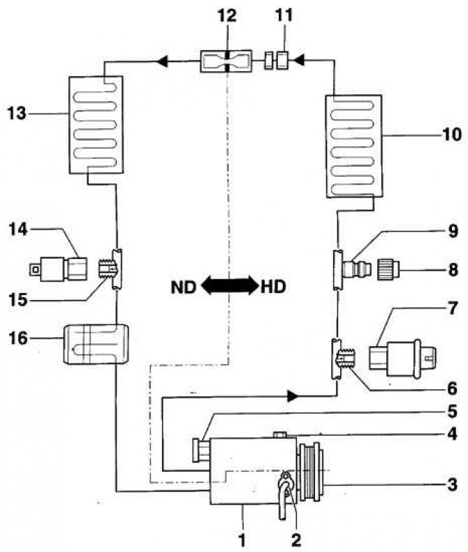


Air conditioning system diagram

  • 1 - compressor;
  • 2 - air conditioning compressor speed sensor;
  • 3 - electromagnetic clutch;
  • 4 - oil drain plug;
  • 5 - excess pressure valve;
  • 6 - connection with valve;
  • 7 - push button switch for air conditioner and electromagnetic clutch;
  • 8 - cap;
  • 9 - service connection;
  • 10 - capacitor;
  • 11 - pipeline connection;
  • 12 - throttle;
  • 13 - evaporator;
  • 14 - push-button switch for the cooling circuit;
  • 15 - valve connection;
  • 16 - capacity;
  • HD - high pressure side;
  • ND - low pressure side

The air conditioning system removes excess heat and moisture from the passenger compartment in accordance with basic physical principles. The refrigerant, circulating as a liquid in the high-pressure section of the system, evaporates and turns into a gas in the low-pressure section. As the gas expands, cooling occurs, accompanied by the removal of heat from the air supplied by the fan to the passenger compartment and a decrease in its temperature. Then, as it passes through the condenser, the refrigerant gives off the absorbed heat to the surrounding air. The heat removal cycle continues indefinitely as the refrigerant circulates in a closed circuit. Moisture is removed from the air supplied to the passenger compartment due to condensation on the evaporator of the refrigeration chamber.


The air conditioning system is a potential hazard. When servicing it, certain rules must be followed. Most repair and maintenance operations on the air conditioning system require special equipment and certain skills.

The body is ventilated by forming a through air flow. Fresh air enters the car through the air intake located in front of the windshield. The air flow exits through the exhaust channels located on the sides of the body near the rear shock absorbers.

The air flow rate is regulated by a four-speed fan.

(The original information is posted on the website: VWmanual)

The mixed air heating system is designed to quickly respond to changes in the air temperature in the passenger compartment and reduce the pulsation of the heated air temperature. The engine cooling system coolant constantly circulates in the heater radiator and the coolant flow is not regulated. The regulated factor is the air temperature, which is changed by the mixing valve, which determines the amount of air passing through the heater radiator before it enters the car's passenger compartment.

To prevent fresh air from entering the car interior, there is an air recirculation mode.

Precautions for servicing the air conditioning system


The air conditioning system is filled with the refrigerant "Freon R12", and the system parts are under operating pressure of over 300 atmospheres. The source of increased danger in case of improper maintenance of the system by untrained technical personnel and when using improper equipment is the high pressure and chemical effect of the refrigerant.


Automotive refrigerant "Freon R12" has a dangerous impact on the environment. In order to protect the environment, Volkswagen prescribes the use of disposal and recycling equipment equipped with an Insurance laboratory (UL) certificate when depressurizing the air conditioning system.

Warning: The air conditioning system must be serviced only by trained technicians who are trained in safe operation, proper equipment, proper depressurization procedures, and are familiar with the collection and storage procedures for vehicle refrigerant.


Warning: Avoid contact with refrigerant on skin.


Warning: Wear safety glasses when working near the air conditioning system.


Warning: If refrigerant gets on your skin or eyes, do not rub the affected area. Rinse immediately with cold water for at least 15 minutes. Seek medical attention or medical attention immediately. Self-medication is not allowed.


Warning: The refrigerant in a new cylinder is stored under pressure. Store the cylinder at a temperature not exceeding 50°C. Take measures to prevent the cylinder from falling from a height or other situations that may cause damage to it.


Warning: Work should be carried out in a well-ventilated area. The refrigerant evaporates quickly, which reduces oxygen supply and makes breathing difficult.


Warning: Gaseous refrigerant is heavier than air and will collect relatively quickly in low places, such as under a vehicle.


Warning: When refrigerant burns, it produces toxic gas. Keep refrigerant away from open flames. Do not smoke. Avoid inhaling smoke when using a flame leak detector.


Warning: When welding near the air conditioning system, always remove the refrigerant from the system. Electric welding near refrigerant pipes may cause the refrigerant to decompose under the influence of ultraviolet radiation.


Warning: Do not expose air conditioning system parts to high temperatures or open flames. Overheating may cause pressure in the system to increase and cause a fire.


Warning: Do not clean the condenser or evaporator with steam. Use only cold water or compressed air.

This article is available at russian, bulgarian, belarusian, ukrainian, serbian, croatian, romanian, polish, slovak, hungarian
The text has been checked: Kolesnikov Artem

Share information:

Previous articles
Air recirculation valve actuator motor
Car interior ventilation
Removal and installation the heater control unit
A damper that regulates the temperature of the air supplied to the passenger compartment
Removal and installation heating and ventilation system control cables
Removal and installation the heater fan and additional resistor
Next articles
Air Conditioning Compressor Brackets


Similar articles from other manuals for VW cars:
Wiring diagram of the Climatronic air conditioning system (part… Passat B6 (2005-2010)
Heating and air conditioning system Polo 3 (1995-2003)
Electrical diagram of the Climatronic air conditioning system Touareg 1 (2002-2006)
Heater and air conditioning system Climatic Tiguan 1 (2007-2015)
Checking the operation of the lighting system Sharan 1 (1995-2000)
Headlight Wash System Transporter T4 (1990-2003)
ESP stabilization system and ASR traction control system Caddy 3 (2003-2010)
Link to this page in different formats


Visitor comments


No comments yet


How much will 49 + 19 =


Golf 5 
  • General information
  • User manual
  • Maintenance
  • Troubleshooting
  • Power unit
  • Engine repair
  • Cooling and ventilation system
  • Fuel system
  • Ignition system
  • Transmission
  • Clutch
  • Mechanical gearbox
  • Automatic gearbox
  • Chassis
  • Brake system
  • Car suspension
  • Steering
  • Body
  • Interior (internal elements)
  • Exterior (external elements)
  • Doors and covers
  • Electrical equipment
  • Power devices
  • Washers and wipers
  • Lighting and appliances
  • Electrical circuits
Golf 4 
  • General information
  • User manual
  • Weekly checks
  • Maintenance
  • Power unit
  • Petrol engines
  • Diesel engines
  • Cooling system
  • Fuel system (petrol)
  • Control system (petrol)
  • Fuel system (diesel)
  • Exhaust system
  • Transmission
  • Clutch
  • Car gearbox
  • Drive shafts
  • Chassis
  • Car suspension
  • Steering
  • Wheels and tires
  • Brake system
  • Body
  • Exterior (external elements)
  • Interior (internal elements)
  • Ventilation and heating
  • Car doors and sunroof
  • Washers and glass cleaners
  • Electrical equipment
  • Power devices
  • Lighting and appliances
  • Electrical circuits
Golf 3 
  • Petrol engine
  • Engine repair
  • Lubrication system
  • Cooling system
  • Ignition system
  • Diesel engine
  • Engine repair
  • Diesel injection system
  • Pre-glow system
  • Transmission
  • Clutch
  • Gearbox and drive shafts
  • Chassis
  • Steering
  • Wheels and suspension
  • Brake system
  • Electrical equipment
  • Lighting and appliances
  • Electrical circuits
Golf 2 
  • General information
  • Introduction to guide
  • User manual
  • Petrol engines 1.3 l
  • Engine repair
  • Lubrication system
  • Cooling system
  • Carburetors
  • Supply system
  • Ignition system
  • Petrol engines 1.6/1.8 l
  • Engine repair
  • Supply system
  • Ignition system
  • Diesel engines
  • Engine repair
  • Lubrication system
  • Cooling system
  • Power and exhaust system
  • Transmission
  • Clutch
  • 4-speed gearbox 084
  • 5-speed gearbox 085
  • 4-speed gearbox 020/4R
  • 5-speed gearbox 020/4T
  • Automatic gearbox
  • Drive shafts
  • Chassis
  • Steering
  • Car suspension
  • Brake system
  • Body
  • Body elements
  • Doors, locks and windows
  • Electrical equipment
  • Equipment and devices
  • Power devices
Golf 2 (petrol) 
  • General information
  • Characteristics
  • Car care
  • Maintenance
  • Power unit
  • Engine repair
  • Engine 1.05/1.30
  • Engine 1.60/1.80
  • Cooling and lubrication system
  • Power and exhaust system
  • Transmission
  • Clutch
  • Car gearbox
  • Drive shafts
  • Chassis
  • Brake system
  • Steering
  • Suspension
  • Body
  • Body and equipment
  • Electrical equipment
  • Lighting and appliances
  • Electrical circuits
Golf 1 (petrol) 
  • General information
  • Characteristics
  • User manual
  • Maintenance
  • Power unit
  • Engine adjustment
  • Engine 1.1/1.3
  • Engine 1.5/1.6/1.8
  • Engine electrical equipment
  • Cooling system
  • Fuel system
  • Transmission
  • Clutch and manual gearbox
  • Automatic gearbox
  • Chassis
  • Steering
  • Front suspension
  • Rear suspension
  • Brake system
  • Electrical equipment
  • Lighting and appliances
  • Electrical circuits
  • Body
  • Body and equipment
  • Optional equipment
Golf 1 (diesel) 
  • General information
  • Specifications
  • Maintenance
  • Power unit
  • Engine repair
  • Exhaust and turbocharger
  • Cooling system
  • Fuel system
  • Fuel injection system
  • Transmission
  • Clutch and drive shafts
  • Car gearbox
  • Chassis
  • Suspension and wheels
  • Steering
  • Brake system
  • Wheels and tires
  • Body
  • Heating and ventilation
  • Exterior (external elements)
  • Interior (internal elements)
  • Doors and windows
  • Electrical equipment
  • Equipment and devices
  • Lighting system
  • Power devices
  • Electrical circuits
VWmanual.ru © 2016-2026 | Mobile version | News and articles | Sitemap: EN BG BY UA RS HR RO PL SK HU | Write message | Site search
Passat B2 • Passat B3 • Passat B4 • Passat B5 • Passat B6 • Golf 1, diesel • Golf 1, petrol • Golf 2, petrol • Golf 2 • Golf 3 • Golf 4 • Golf 5 • Polo 3 • Polo 4 • Touareg 1 • Tiguan 1 • Sharan 1 • Transporter T3 • Transporter T4 • LT 28 • LT 2D • Beetle • Caddy 3 •
Our website uses cookies to ensure functionality and convenience.