
From the housing, unscrew the two bolts that secure the gear selection rod and the V gear gear.
Turn out the switch of lanterns of a backing.
Remove the bolt (IN) (see fig. 334), if the car is equipped with an indicator of the selected gear and fuel consumption.
Using a spark plug wrench, unscrew the bolt blocking the gear selector rod. Remove the spring, set the gear selectors to neutral and remove the shaft. In another position, the shaft cannot be removed.
From the clutch side, remove the drive va-pa flange. To do this, it is necessary to remove the plastic lining and the retaining ring from the flange, which fixes the flange on the shaft. Remove the gasket placed under it. Fasten the special puller with two bolts to the flange and, screwing the puller nut, remove the flange from the shaft (see fig. 336).
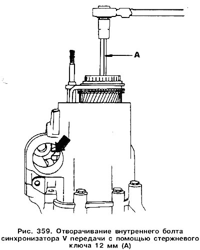
From the middle of the synchronizer hub, unscrew the bolt using a 12 mm rod wrench (Polygon). The bolt is very tight, so you should use an additional wrench on the end of the rod wrench (pic. 359). To block the shaft, you need to include V gear and reverse (by moving the forks down through the left hole).
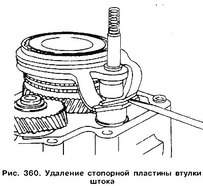
Remove the plate securing the stem sleeve with a screwdriver (pic. 360).
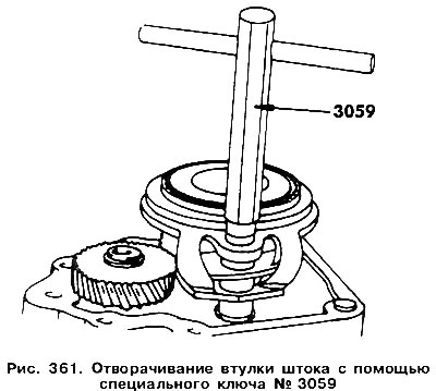
Unscrew the sleeve using a special key Nq 3059 (pic. 361). Turn the key to the left. You can not remove the stem from the bushing.
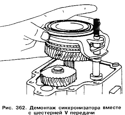
Remove the V gear together with the synchronizer and forks (pic. 362).
Remove the circlip and spring washer of the 5th gear and use a puller to remove the gear from the shaft.
Use a 6 mm hexagon wrench to unscrew the input shaft bearing plate bolt.
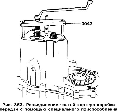
Loosen the bolts connecting both parts of the crankcase and separate them, helping with blows of a rubber hammer. If you have difficulty, use a puller (pic. 363). When the gearbox housing is divided, you can proceed to further disassembly and repair. On fig. 364 shows the components and parts that have been dismantled by this moment.
Attention! In the case of replacing one of the halves of the crankcase or the input shaft, be sure to calculate the thickness of the bearing shim.
The procedure for dismantling the primary and secondary shafts described here.
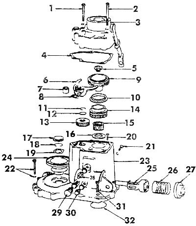
Pic. 364. Knots and details of a five-speed gearbox: 1, 2, 22, 31 - bolts (25 Nm); 3 - crankcase cover; 4 - gasket: 5 - bolt (150 Nm); 6 - V gear forks; 7 - spacer sleeve (currently not installed); 8 - locking plate; 9 - synchronizer V transmission; 10 - synchronizer blocking ring; 11, 18 - retaining rings; 12, 16 - spring washers; 13 - gear V gear; 14 - gear IV gear; 15 - needle bearing; 17 - plug (always replaceable); 19 - curly gasket; 20 - bolt (15 Nm); 21 - bolt (30 Nm); 23 - crankcase I gearbox; 24 - flange of the axle drive shaft; 25 - gear shift shaft; 26 - spring; 27 - cover; 28 - light switch, reverse; 29 - a bolt of blocking of V transfer; 30 - a bolt of blocking of a shaft of a gear change
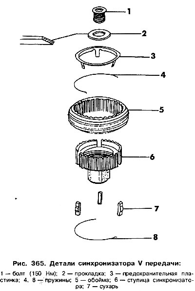
Dismantling the main gear described here. The components and parts of the input shaft located in the gearbox housing are shown in fig. 364. After their dismantling, the shaft looks as shown in rice. 343. Details of the V transmission synchronizer are shown in fig. 365. Disassembly of the primary and secondary shafts is carried out in accordance with rice. 343 and 340.
After disassembling the gearbox, check its parts, as it was described here.
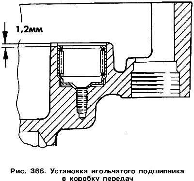
If there is a need to replace an additional bearing, it must be removed using an impact puller. A new bearing is installed with the markings facing in until its edge is 1.2 mm deep into the hole in the gearbox housing (pic. 366).
Visitor comments