



Disconnect the lever from the gear selector rod, placing the gearbox on the "gap".
Loosen locknut 2 (figure 371) and screw in bolt 1 until retaining ring 4 comes away from the bolt.
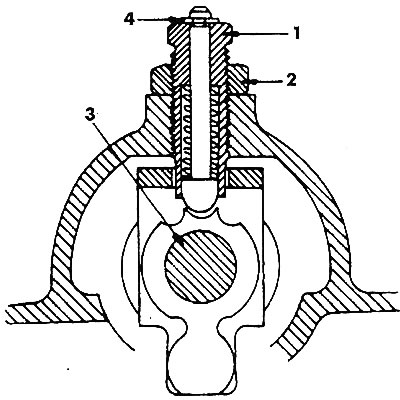
Figure 371. Gear shift shaft locking mechanism: 1 - adjusting bolt; 2 - lock nut; 3 - gear shift shaft; 4 - retaining ring
Unscrew the bolt again until it touches the retaining ring and tighten lock nut 2.
Check by slightly turning rod 3 whether ring 4 has risen.
To adjust the 5th gear locking bolt, do the following:
- Set the gearbox to "gap".
- Remove the cap from bolt 29 (see figure 364). Loosen locknut 2 (figure 372) and screw in bolt 1 until pin 3 is raised.
- Loosen the bolt by 1/3 of a turn and tighten the lock nut 2.
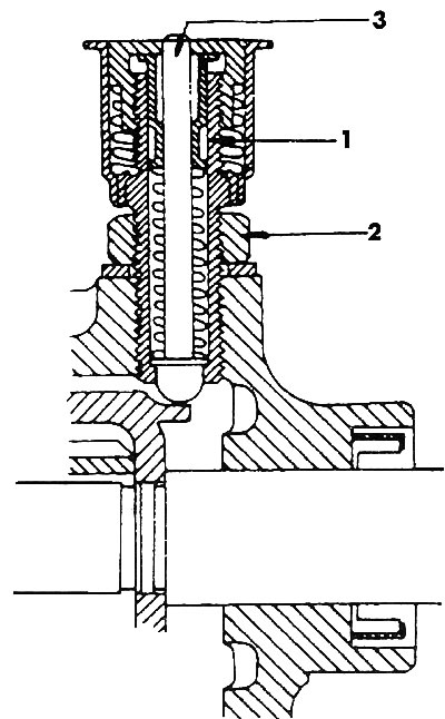
Figure 372. 5th gear locking mechanism: 1 - V gear adjustment bolt; 2 - lock nut; 3 - pin
Visitor comments