



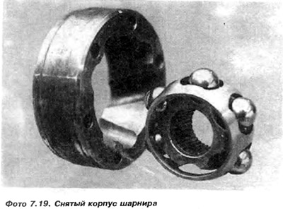
43. Insert the balls into the basket slots (photo 7.19)
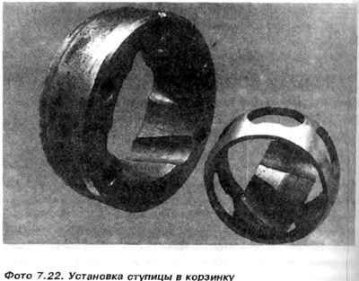
44. Install the basket with the hub perpendicular to the joint housing and slide it into the corresponding grooves. Install the basket with the balls, and then turn it 90° in the direction of the larger spacing of the ball track grooves, as shown by the arrow, to install it parallel to the plane of the joint (photo 7.23)
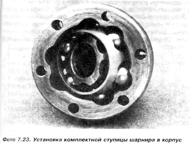
Please note that after assembly, the groove on the hub splines should be on the rubber casing side. Determining the required position will facilitate preliminary: marking of elements before disassembly.
45. Check whether the hub moves freely in its working semicircle.
46. Install the inner joint housing 8 on the axle shaft 9, and then the concave spring washer 7 (figure 7.1).
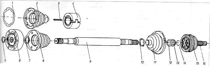
Figure 7.1. Drive axle assembly
1 - gasket used in gti version; 2 - gti hinge housing; 3 - spring peg; 4 - shock absorber; 5 - landing ring; 6 - internal drive joint; 7 - toothed concave washer; 8 - hinge housing; 9 - drive axle; 10 - casing clamping belt; 11 - hinge housing; 12 - spring washer; 13 - cone washer; 14 - spring ring; 15 - drive joint housing; 16 - short axle shaft.
Note that this washer is larger than the similar washer on the outer hinge and has teeth (photo 6.17).
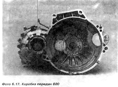
The washer must be facing the concave side towards the joint hub.
47. Secure the axle shaft in a vice or press, then drive or press the joint onto the axle shaft using a suitable metal tube 1, striking the hub of the joint.
48. Install the safety spring ring into the groove.
49. Squeeze grease into the joint, then move the casing onto the joint body.
50. Install the rubber boot back onto the axle shaft so that it is not deformed after installation and its outer end matches the mark made during disassembly.
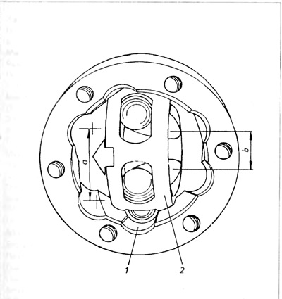
Figure 7.5. Installing the hub and basket into the housing
1 - ball track groove; 2 - basket; a - smaller distance between track grooves; b - greater distance between track grooves.
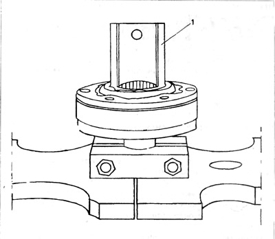
Figure 7.6. Pressing the hinge onto the axle shaft
1 - tube.
Visitor comments