



Note: If only the tappet protection tubes are defective or the tappet protection tube sealing rings need to be replaced, it is not necessary to remove the cylinder head. Telescopic tappet protection tubes are available at service stations for subsequent engine modification.
Removal
The cylinder heads can be removed without removing the engine. In this case, it is only necessary to drain the coolant first.
Unscrew the engine protection from below.
Disconnect the spark plug caps.
Remove the muffler and both exhaust pipes.
Remove the intake manifold with the carburetor.
Flush the engine in gasoline, especially in the area of the cylinder heads.
Warning: Fire hazard, do not use open flames.
Unscrew the coolant pipe from the right cylinder head and remove it from the left cylinder head,
On the left cylinder head, remove the water hose leading to the cylinder head from the coolant temperature sensor flange.
Disconnect the ground wire from the left cylinder head.
Use a powerful screwdriver to press the cover clamp down.
Remove the cover and rinse before installation.
Unscrew the 2 rocker arm shaft mounting bolts.
Remove the shaft with rocker arms.
Pull out the pushers.
Unscrew 8 nuts (see the "Installation" section for location) and remove with washers.
Remove the cylinder head with the gasket and the protective tubes of the tappets.
Note: If the hydraulic tappets are also removed, they should be marked so that they can be installed in the same holes later. Store crushed tappets with the tappet bottom facing down.
Installation
Before installation, remove deposits in the cylinder/cylinder head area.
Sealing between the cylinder and the combustion chamber is achieved in each cylinder by installing a metal sealing ring. These sealing rings must be replaced at each disassembly.
Before installation, check the cylinder head for cracks in the combustion chambers and exhaust channels. You should also check the contact surfaces of the cylinder linings and the intake manifold flange. Damaged heads are replaced.
If there are small cracks (0.5 mm) between the valve seat sleeve and the spark plug hole thread, or if only the first turns of the spark plug hole thread are damaged, the heads can be installed on the engine.
If the hydraulic tappets were removed, insert them into their original places in accordance with the markings made. Check the tappets first.
Check the integrity and reliability of the fastening of the threaded spark plug holes and studs. Damaged or overtightened threads are corrected using Heli-Coli thread inserts.
If the rocker shafts were disassembled, check the wear of all parts. Replace damaged parts and assemble.
Check the tappets for bending. The runout should not exceed 0.3 mm. To do this, place the tappets on a flat surface and measure the runout using feeler gauges.
If there are scratches on the working surface of the rocker arms and support posts, they can be removed with fine sandpaper. To do this, place the sandpaper on a flat surface.
Before installation, arrange the old pushrod protective tubes to the required size.
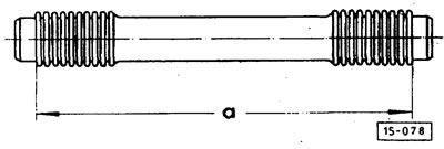
Tighten the tappet protection tubes. Dimension "a" is about 194 mm.
Carefully install the cylinder head with new metal sealing rings. When installing the tappet protection tubes, ensure that the sealing rings are correctly seated between the engine case and the protection tube, as well as between the cylinder head and the protection tube.
Caution: Install new O-rings for the pushrod protective tubes.
Turn the protective tube with the seam facing up.
For better sealing of unpainted or painted contact surfaces on the cylinder head, VAG sealing compound D 000400 is used.
If the paintwork is damaged, treat the contact surface of the cylinder head on the engine crankcase with fine sandpaper.
Wash the contact surfaces with gasoline.
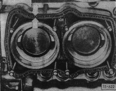
Apply a 1-2 mm thick layer of sealing mass "arrows" in the middle of the gasket. To do this, cut the syringe of the tube at an angle.
Caution: Do not apply too thick a layer of sealant. It may clog the coolant passages in the cylinder head.
The cylinder head must be tightened no later than 45 minutes after applying the sealing compound.
Install the cylinder head with a new gasket. Ensure that the cylinder head gasket is seated correctly.
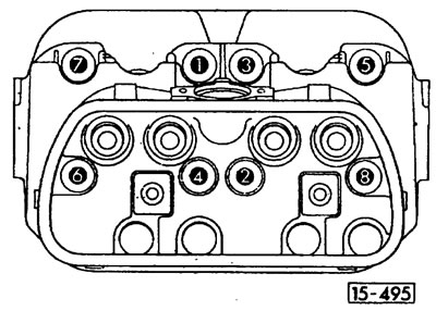
Tighten the cap nut on stud "1" without the washer until the remaining nuts with the washer can be tightened by hand.
Caution: Coat the cleaned and degreased contact surfaces of the cap nuts and washers with sealing compound VAG AKD 45600001 and pre-tighten in the correct sequence - from 2 to 8 - with a torque of 10 Nm.
Unscrew the cap nut from stud "1". Clean and open the AKD 45600001 washer on both sides and pre-tighten the nut to 10 Nm.
Caution: Ensure correct seating of the tappet protective tubes.
Finally tighten the cap nuts with a torque wrench from 1 to 8 to 50 Nm.
Push in the pushrods and place the rocker arm shaft onto the mounting pins.
Caution: Carefully insert the push rods into the push rod ball bearings. Control with your finger. Push rods installed on the edge of the push rod will result in incorrect adjustment results and damage to the push rods when turning the engine.
Before installing the rocker shaft, loosen the base adjustment screws until they are flush with the rocker arms.
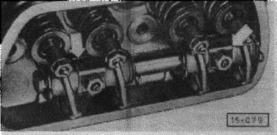
Note: Make sure that the slots in the support posts (arrows) are facing upwards.
Use M8 nuts for fastening. Tighten the nuts to a torque of 25 Nm.
Perform basic valve clearance adjustment.
Install the intake manifold with the carburetor.
Install water hoses.
Fill with coolant.
Install the exhaust system.
Install the left cylinder head ground wire.
Put on the spark plug caps.
Screw the lower protective covers under the car.
Check the engine oil level.
Once operating temperature is reached, check the coolant level and top up if necessary.
Check idle speed and readjust if necessary.
After a test drive, check for coolant leaks and, if necessary, tighten the hose clamps.
Removal air from the tappets
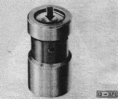
Tappets with valve clearance compensation must be checked for air inclusions in the working chamber after installation. A finger press test is sufficient for this. The piston must not yield to strong finger pressure (in the direction of the arrow). Otherwise, it is necessary to remove air from the plunger.
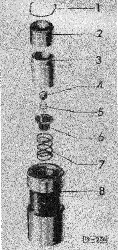
Pull out the retaining ring "1" and remove the push rod bushing "2", the piston with valve -3,4,5,6- and the valve spring "7".
Fill plunger "8" up to hole "9" with oil.
Insert spring "7".
Insert piston "3" with valve -4,5,6- and press down. At the same time, open ball valve "4" with a reamer.
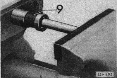
Insert the push rod bushing and the valve guide bushing or cut push rod and squeeze it in a vice (with the hole "9" facing up) or in a repair press until the retaining ring "1" can be inserted.
Insert retaining ring "1".
Visitor comments