
Raise the luggage compartment floor. Remove spare wheel. Now it is» access «to the marks -1-, on the floor of the luggage compartment. -Arrow- indicates the direction of the vehicle.
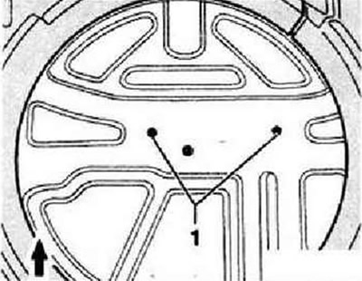
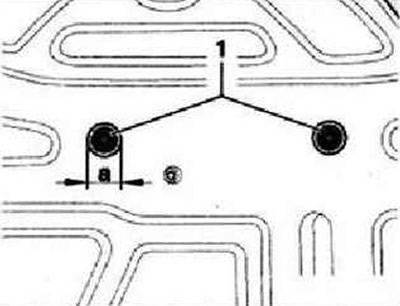
Drill 2 holes at the marks -1- for the dimension -a- = 26 mm 0. If possible, extract the chips when drilling. Remove burrs from holes and remove chips carefully. Restore the manufacturer's anti-corrosion coating with special materials.
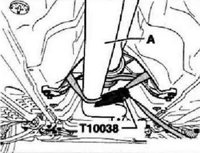
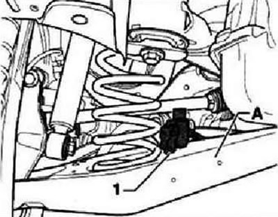
Loosen and remove both bolts -1-. These bolts will need to be replaced later. Raise the car. Remove stabilizer. Secure front exhaust pipe -A- with tie-down strap -T10038- to intermediate support for propshaft.
Unscrew the exhaust pipe bracket from the subframe.
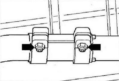
Loosen clamps -arrows- and remove rear section of exhaust system. Remove the soundproof cover under the power unit.
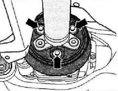
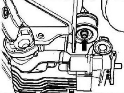
Remove screws -1- and -2- for oscillating bearing. In order not to damage the vehicle level sender at rear left -G76-...
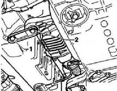
...disconnect the connector, unscrew the sensor and place it on the support arm -A-.
Only loosen intermediate bearing for propshaft -arrows-, do not unscrew.
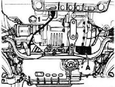
Press the engine and gearbox forward by hand and secure them in this position with a suitable piece of wood -A-.
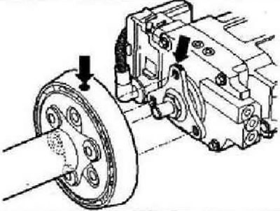
To avoid noise later due to imbalance. Check for tags (paint dot) on the flexible coupling and the flange/propshaft of the rear final drive -arrows- If missing, mark the position of the flexible coupling and the flange of the rear final drive input shaft in relation to each other -arrows-.
Unbolt propshaft from rear final drive -arrows-.
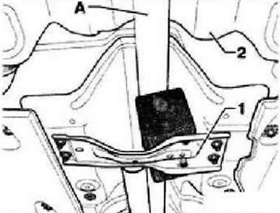
Detach propshaft from final drive and guide upwards in the middle to fuel tank -2-. Support in this position on a suitable piece of wood on the tunnel support -1-.
Caution: Do not press on the trampled tank -2-.
To be able to remove and install the drive shafts, the main gear in the rear area must be movable.
To do this, unscrew the bolt -arrow- on the front support cushion by no more than 5 turns. Unscrew the drive shaft to the left of the final drive.
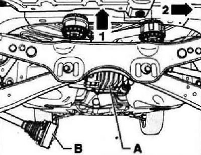
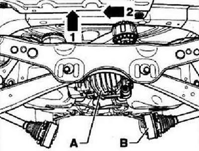
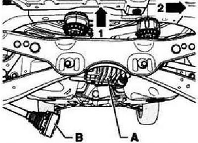
Raise final drive -A- at rear -arrow 1- and move as far to the right as possible -arrow 2-. Remove left drive shaft -B- from flange and guide downwards carefully. Place final drive back into installation position. Unscrew the drive shaft to the right of the final drive.
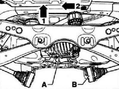
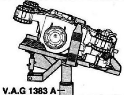
Raise final drive -A- at rear -arrow 1- and move as far to the left as possible -arrow 2-. Remove right drive shaft -B- from flange and guide downwards carefully. Place final drive back into installation position. Grip final drive with jack -VAG 1383 A- and secure it to universal support with belt.
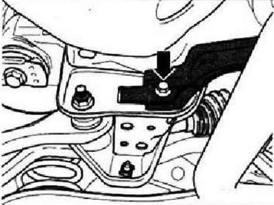
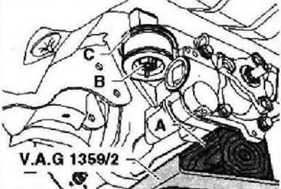
Unscrew bolt -arrow- on front support cushion. This bolt will need to be replaced later. Remove the washer at the top -C- on the support pad.
Install the final drive into the vehicle at an angle as shown in the figure and lower it slightly at the same time.
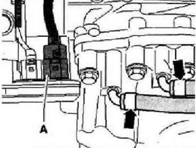
Disconnect electrical connector -A- from four-wheel drive control unit -J492-. Detach ventilation hoses -arrows- from rear final drive. To remove the main gear, lower it further and pull «forward». focusing on sufficient "free play" in relation to other elements.
Installation
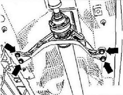
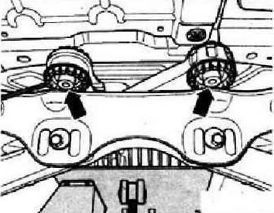
Secure the main gear against falling with the universal support belt. Move final drive to position shown. Raise final drive and guide rear bearings -arrows- over subframe; keep track of the free distance to other nodes.
Connect connector -A- to four-wheel drive control unit -J492-. Push vent hoses -arrows- onto vent nipple of final drive. Raise the main gear with the transmission rack to the installation position. Lay washer -C- on support pad. To be able to remove and install the drive shafts, the main gear in the rear area must be movable. Screw in the front fixing bolt by hand, leave free no more than 5 turns. Remove the transmission rack from under the vehicle. Raise final drive -A- at rear -arrow 1- and move as far to the left as possible -arrow 2-. Carefully insert drive shaft from right -B- upwards 80 flange. Place final drive back into installation position. Screw the drive shaft on the right to the final drive.
Raise final drive -A- at rear -arrow 1- and move as far to the right as possible -arrow 2-. Carefully guide drive shaft from left -B- upwards into flange. Place final drive back into installation position. Screw the drive shaft on the left to the final drive. Tighten propshaft in final drive.
Tighten» bottom «fastening -arrow-of the final drive. Attach drive shafts. Attach the lower support of the power unit «new» bolts. Install soundproofing. Loosely align intermediate support and secure. Install rear left vehicle level sender -G76-. Carry out the basic setting of the headlights using the Vehicle diagnosis, testing and information system VAS 5051. Install the exhaust system. Install stabilizer. Insert» new «bolts -arrow- through holes in luggage compartment floor and tighten down. Close holes. If final drive is to be replaced: check oil level in Haldex clutch. Check the oil level in the final drive.
Visitor comments