



Removal
1. Disconnect the negative cable from the battery.
2. Drain the coolant.
Caution! The fuel system is under pressure! Place a rag around the connection before loosening the quick-release fasteners. Then, by gently pulling on the tube, relieve the pressure.
3. Disconnect the fuel supply and return lines (arrows) (figure 2.8).
4. Disconnect the accelerator pedal cable.
5. Disconnect the oil level indicator pipe from the cylinder head.
6. Disconnect the front section of the exhaust pipe from the exhaust manifold.
7. Disconnect all wires from the cylinder head.
8. Disconnect the coolant pipes from the thermostat housing.
9. Disconnect the thermostat housing from the upper cover of the distribution mechanism.
10. Remove the upper timing cover.
11. Loosen the camshaft gear mounting bolts.
12. Set the crankshaft to 20° after TDC (figure 2.18).
13. Insert the 3436 locking tool into the inspection holes of both camshafts and lock them in place (figure 2.19).
14. Unscrew the bolts and remove the upper damper bar 1 (figure 2.27).
15. Unscrew the camshaft gear mounting bolts.
16. Using the VW 771/1 puller and the VW 771/39 adapter, press out the bearing cap bolt (figure 2.39).
17. Unscrew the internal hex bolts A (figure 2.40).
18. Unscrew the cylinder head mounting bolts. Unscrewing the mounting bolts is carried out in the reverse order to that shown in the figure 2.40.
19. Remove the cylinder head.
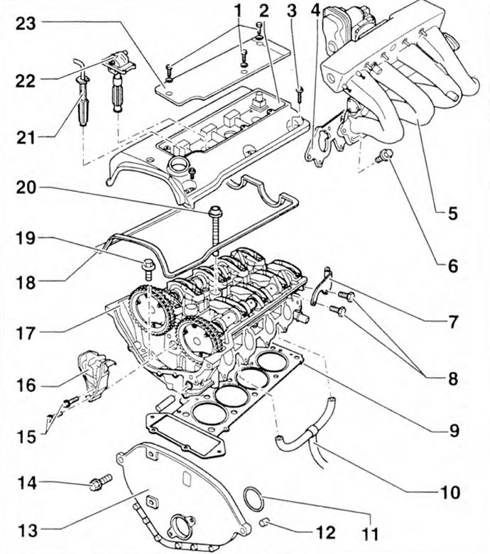
Figure 2.38. Cylinder head: 1, 3, 6, 8, 14, 15, 19, 20 - Bolts; 2 - Cylinder head cover; 4 - Gasket; 5 - Intake manifold; 7 - Bracket: 9 - Cylinder head gasket; 10 - Engine crankcase ventilation tube; 11 - Seal; 12 - Adjusting sleeve; 13 - Upper cover of the distribution mechanism; 16 - Upper damper bar; 17 - Cylinder head; 18 - Cylinder head cover gasket; 21 - Spark plug wire tip; 22 - High voltage transformer; 23 - Spark plug protective cover.
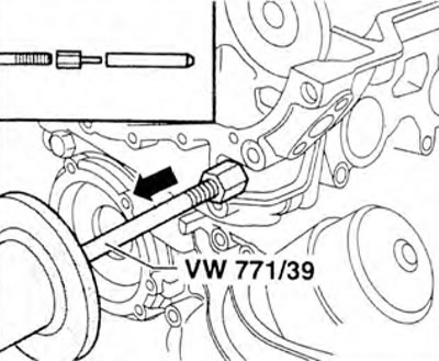
Figure 2.39. Using the VW 771/1 puller and the VW 771/39 adapter, press out the bearing cap bolt.
Installation
20. Carefully remove the remaining gasket. When doing this, be careful not to create long grooves or scratches (when using sandpaper, the granulation cannot be lower than 100). Carefully remove any remaining sandpaper and lapping compound.
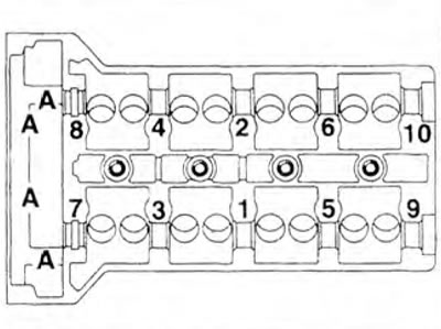
Figure 2.40. Unscrew the internal hex bolts A.
21. Install the cylinder head gasket. Observe the mounting position of the adjusting bushings in the cylinder block.
22. Install the cylinder head.
23. Check the length L of the cylinder head bolts, replace if necessary (figure 2.41). Nominal length L: 102...105 mm.
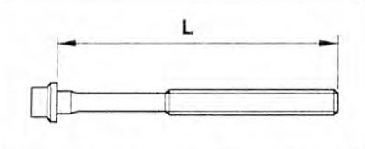
Figure 2.41. Checking the length of the cylinder head mounting bolts.
24. Install the cylinder head bolts and tighten them by hand.
25. Tighten the cylinder head in three stages in the order shown in the figure 2.40: stage I = 55 Nm; stage II = 1/4 turn (90°), stage III = 1/4 turn (90°).
Please note! Tightening the cylinder head bolts after repair work is not required.
26. Tighten the internal hex bolts A (figure 2.40).
Tightening torque: 20 Nm.
27. Install the bearing cap bolt.
28. Install the camshaft drive chain onto the drive gears.
29. Tighten the camshaft drive gear mounting bolts (the camshafts are held with a 3437 wrench).
Tightening torque: 20 Nm + 1/4 turn (90°).
30. Install the upper damper bar 1 (figure 2.27).
Tightening torque: 10 Nm.
31. Install the timing chain tensioner.
32. Install the upper timing cover.
33. Remove camshaft locking pins 3436 (figure 2.19).
34. Check the valve timing.
35. Install the cylinder head cover. Subsequent installation is carried out in the reverse order of removal.
Examination
36. Check the cylinder head for deformation (figure 2.42).
Maximum permissible deformation: 0.1 mm.
Visitor comments