




List of parts and assemblies with notes on installation work for Figure VC2.147:
1. Oil pump.
2. Oil pump mounting screw: 15 Nm.
3. Oil pump drive sprocket.
4. Bearings 1, 2, 3, 4 and 5 of the crankshaft bearings are installed:
- in the cover - without a lubrication groove;
- in the cylinder block - with a lubrication groove;
- previously used liners cannot be swapped (mark when removed).
5. Main bearing cap mounting screws; 40 Nm and tighten by 90° (1/4 turn):
- replace with a new one during assembly;
- thread to head;
- to measure the radial clearance, tighten to a torque of 40 Nm, without tightening by 90°.
6. Main bearing caps:
- bearing cover 1: from the poly V-belt pulley side;
- the retaining protrusions of the liners installed in the cylinder block and in the covers must be installed opposite each other.
7. Bearing insert 3:
- previously used liners cannot be swapped (mark when removed).
8. Engine speed sensor timing rotor (G28);
- the timing rotor should be replaced with a new one after each unscrewing of the fastening screws;
- installation is possible only in one position (the holes are located with an offset).
9. Timing rotor mounting screw: 10 Nm and tighten by 1/4 turn (90°):
- replace with a new one during assembly.
10. Crankshaft:
- permissible values of axial run-up;
- for new: 0.07-0.23 mm;
- maximum permissible value: 0.30 mm;
- the radial clearance should be determined using a Plastigage plastic gauge;
- for new: 0.01-0.04 mm;
- maximum permissible value: 0.07 mm;
- when measuring the radial clearance, do not rotate the crankshaft.
11. Thrust half ring:
- installed in the cylinder block on both sides of the 3rd main bearing;
- the inscription must face the bearing.
Apply the sealant as shown in the figure (arrows) to the degreased contact surface of the cover. The thickness of the sealant strip should be 2-3 mm.
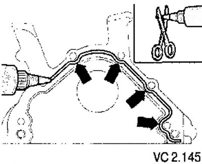
Notes on crankshaft rear cover installation technology
Before applying the sealant, protect the oil seal with a clean cloth.
The thickness of the sealant layer should not be more than 2-3 mm, otherwise the sealant protruding from the joint may get into the oil pan and lead to clogging of the oil receiver mesh.
The sealant must not be expired.
The oil pan must be installed within 5 minutes of applying the silicone sealant.
The installation of the cover together with the seal is carried out using a guide sleeve.
After installing the part, wait approximately 30 minutes for the sealant to dry. Only after this can you add engine oil.
After this, immediately install the cover, lightly tightening the screws by hand.
Tighten the cover mounting screws. Tightening should be done evenly, tightening opposite screws in pairs. Tightening torque: 15 Nm.
Remove excess sealant that has come out of the joint between the parts during tightening.
Install the oil pan.
If the cover was installed without a seal, install the seal.
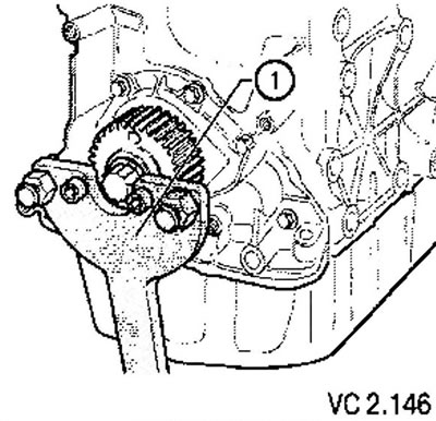
Install the crankshaft timing pulley and secure it with a holding device.
Attention!
- There should be no oil on the mating surfaces of the toothed pulley and the crankshaft.
- Replace the center screw with a new one.
- There should be no traces of oil on the threads and bearing surface.
- Tighten the new center screw to 90 Nm, then turn it an additional 1/4 turn (90°) (turning can be done in several stages).
Further installation is carried out in the reverse order of removal.
Attention!
- Before removing the crankshaft, it is necessary to provide a place to place the parts to be removed so that the timing rotor is not damaged.
- To carry out installation work, the engine must be installed on an assembly stand for engines and transmission units.
Visitor comments