
Attention! If a large amount of metal chips and other wear products are found in the engine oil during engine repair, this may indicate damage to the connecting rod or main bearings of the crankshaft. To avoid subsequent damage after repair work, it is necessary:
- thoroughly clean the oil channels;
- replace the oil filter;
- replace piston cooling jets (if they are installed);
- replace oil cooler.
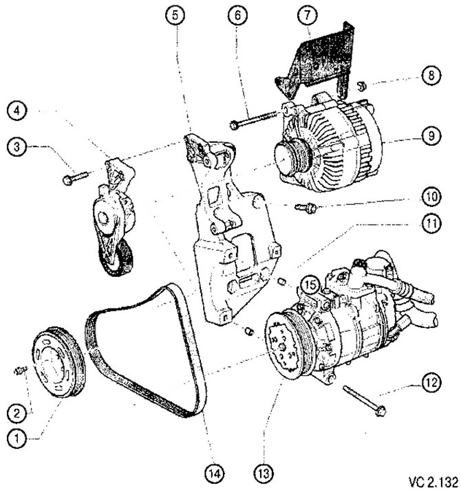
List of parts and assemblies with notes on installation work to Figure VC2.132:
1. Crankshaft pulley (auxiliary drive V-ribbed belt).
2. Screw: 10 Nm, tighten 90° (1/4 turn):
- when assembling the engine, replace the screw with a new one.
3. Screw: 23 Nm.
4. Poly V-belt tensioner:
- to loosen the tension of the V-ribbed belt, the tensioner must be turned with an open-end wrench.
5. Bracket for attaching auxiliary mechanisms of mounted units:
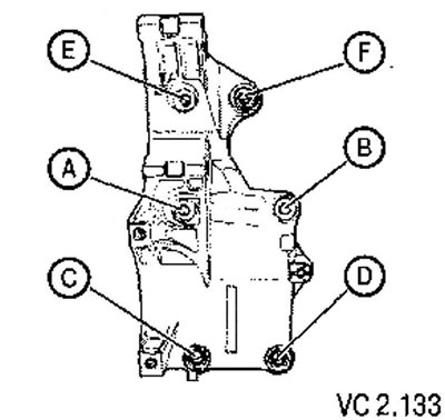
- follow the tightening sequence (see below).
6. Bolt (nut - pos. 8).
7. Shield.
8. Nut: 23 Nm.
9. Generator:
- to facilitate the installation of the generator, lightly press the threaded bushings under the supporting screws of the generator into place.
10. Auxiliary bracket mounting screw: 45 Nm:
- follow the tightening sequence (see below);
- Dacromet coated screws (the whole screw has a greenish tint) must be replaced with new ones during reassembly.
11. Sleeve (2 pcs.).
12. Air conditioning compressor mounting screw: 25 Nm.
13. Air conditioning compressor.
14. V-ribbed belt:
- before removing, mark the direction of belt movement with chalk or a felt-tip pen;
- check for wear;
- do not bend.
Attachment Bracket Tightening Sequence
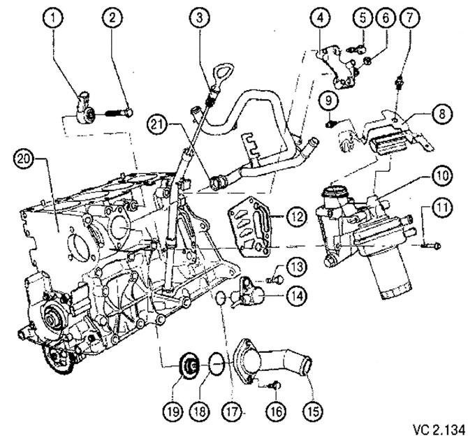
List of parts and assemblies with notes on installation work to Figure VC2.134:
1. Knock sensor 1 (G61):
- Contacts are gold-plated.
2. Knock sensor mounting screw: 20 Nm:
- the tightening torque affects the operation of the knock sensor.
3. Oil dipstick;
- the oil level must not be higher than the max mark!
4. Ignition coil bracket.
5. Ignition coil bracket screw: 10 Nm.
6. Nut: 10 Nm.
7. Screw: 10 Nm.
8. Bracket.
9. Screw: 6 Nm.
10. Oil filter bracket.
11. Oil filter bracket screw: 15 Nm, tighten 1/4 turn (90°).
12. Gasket:
- when assembling, replace with a new one.
13. Screw for fastening the engine speed sensor: 10 Nm.
14. Engine speed sensor (G28).
15. Branch pipe of the cooling system.
16. Screw for fixing the thermostat cover: 15 Nm.
17. O-ring:
- when assembling, replace with a new one.
18. O-ring:
- when assembling, replace with a new one.
19. Thermostat:
- test by heating in a vessel with water;
- start of opening; about 85°C;
- full opening: approximately 105°C;
- valve lift height: not less than 7 mm.
20. Cylinder block.
21. O-ring of the cooling system pipe:
- when assembling, replace with a new one.
Visitor comments