



The plastic spacers that protect the exposed valves should only be removed immediately before installing the cylinder head.
When replacing the cylinder head, you should also drain the old coolant and fill it with new coolant.
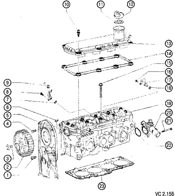
List of parts and assemblies with notes on installation work for Figure VC2.156:
1. Timing belt cover rear plate fastening screw: 23 Nm:
- Apply thread locking compound.
2..Toothed pulley of the camshaft.
3. Camshaft timing pulley fastening screw: 100 Nm:
- When loosening and tightening, use a lever to hold.
4. Timing belt cover rear plate fastening screw: 10 Nm:
- Apply thread locking compound.
5. Rear plate of the timing belt housing
6. Prismatic key.
7. Sealing ring:
- Replace with a new one during assembly.
8. Screw for fastening the branch pipe for removing steam locomotive plugs 10 Nm.
9. Pipe for removing air and steam locks.
10. Special bolt: 9 Nm:
- Replace if damaged or leaking.
11. Oil filler cap gasket.
12. Oil filler cap.
13. Valve cover:
- When removing, loosen the mounting screws from the edges to the middle;
- When installing, tighten the mounting bolts from the middle to the edges.
14. Valve cover gasket.
15. Cylinder head fastening screw:
- Replace with a new one during assembly;
- Observe the sequence when loosening and tightening.
16. Camshaft position sensor mounting screw: 10 Nm.
17. Hall sensor (G40).
18. Sealing ring.
19. Cylinder head.
20. Cooling system pipe.
21. Pipe mounting screw: 10 Nm.
22. Sealing ring.
23. Cylinder head gasket:
- Mounting position: The part number in the catalog must face upwards, towards the cylinder head, and be read correctly (not to be turned upside down) when viewed from the intake manifold;
- After replacing the gasket, replace the coolant.
Visitor comments