
English Русский
Български
Беларускі
Український
Српски
Hrvatski
Română
Polski
Slovenský
Magyar
  |  Articles  |  Sitemap  |  Contacts  |    |
Car maintenance Ford Car maintenance Hyundai Car maintenance Chevrolet Car maintenance BMW Car maintenance Audi Car maintenance Opel Car maintenance AvtoVAZ
VWmanual.ru


Main   Passat   Golf   Polo   Touareg   Tiguan   Sharan   Transporter   Others  
LT 28 (1975-1991) LT 2D (1996-2003) Beetle (1960-1986) Caddy 3 (2003-2010)

Removal and installation the cylinder head (VW Caddy 3)

  • Main
  • Volkswagen
  • Caddy 3
  • Diesel engines
  • Engine repair
  • Removal and installation the cylinder head
            0


Contents: Removal ↓ Installation ↓
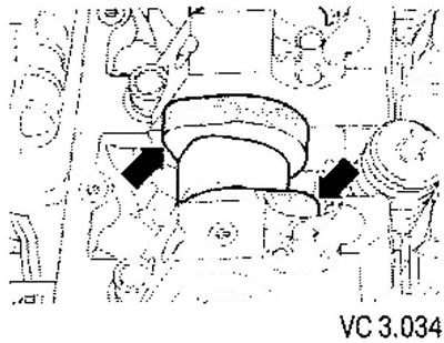
Attention! Since 05.2005 a modified front (right in the direction of the vehicle) an engine mount that no longer requires removal when replacing the timing belt.


The figures below can be used to determine which engine mount is installed in the vehicle.
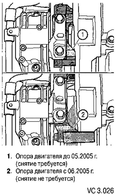
The figures below can be used to determine which engine mount is installed in the vehicle.


Caution! After assembly, reinstall all cable ties removed or cut during cylinder head removal.


Removal


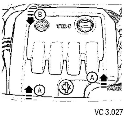
1. Remove the engine cover by pulling it firmly upwards (arrows A) and then forwards (arrow B), disengaging it from the rear mount.

2. Remove the water drain box shield.

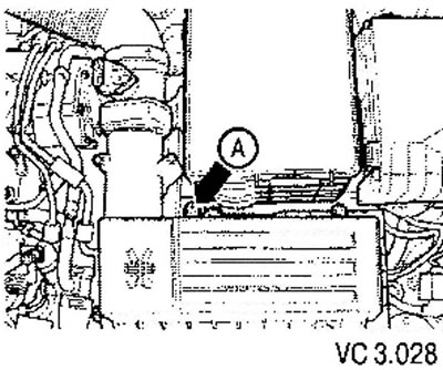
3. Remove the air filter housing with the air flow meter and connecting tube.
3. Remove the air filter housing with the air flow meter and connecting tube.


4. Loosen the screw (arrow A) and move the air filter housing upwards from the mount.


5. Remove the soundproofing casing.

6. Drain the coolant.

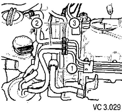
7. Before removing the cylinder head, use a hand vacuum pump to pump out the fuel from the dual pump.
7. Before removing the cylinder head, use a hand vacuum pump to pump out the fuel from the dual…


8. Disconnect the pressure (2) and return (1) line hoses, as well as the cooling system hose (3).

9. Remove the fuel filter module from its mount and, without disconnecting the hoses, set it aside.

10. Remove the exhaust pipe.

11. Remove the turbocharger support and oil return line from the turbocharger (for 1.9 L engines).

12. Remove the turbocharger oil supply line and set it aside.

13. Remove the timing belt.

14. Remove the timing belt tension roller.
14. Remove the timing belt tension roller.


15. Remove the camshaft toothed pulley hub.

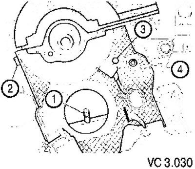
16. Unscrew the screws securing the rear timing belt cover (2) and (4).


17. Unscrew the camshaft position sensor (3) (G40).

18. Remove the EGR system connecting pipe.

19. Disconnect all other wires that need to be disconnected from the cylinder head and set them aside.

20. Disconnect all connecting pipes, cooling system hoses, vacuum hoses and air ducts from the cylinder head.
20. Disconnect all connecting pipes, cooling system hoses, vacuum hoses and air ducts from the…


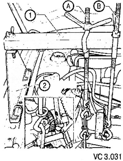
Please note: Both lifting eyes are located on the cylinder head, so to support the engine on the cylinder block, you must attach an additional bracket.


21. Suspend the engine so that the weight of the power unit is not applied to the cylinder head.
21. Suspend the engine so that the weight of the power unit is not applied to the cylinder head.


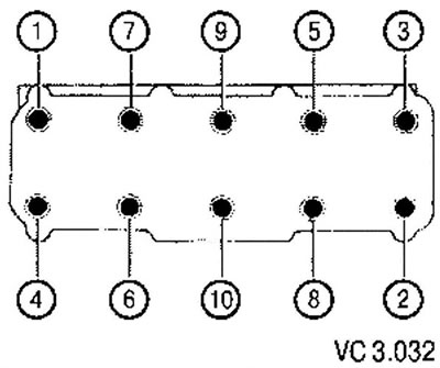
22. Loosen the cylinder head mounting screws in the sequence shown in the figure, then unscrew the screws and remove the cylinder head.

In vehicles produced since 06.2005, the tension roller remains in the engine mount.
In vehicles produced since 06.2005, the tension roller remains in the engine mount.


Installation


Attention!
  • Always install new cylinder head bolts.
  • When repairing, it is necessary to carefully remove the remaining gasket from the cylinder head and from the cylinder block. Avoid leaving scratches on the mating surfaces.
  • Carefully remove any remaining abrasive and polishing compounds.
  • The new cylinder head gasket should be removed from its packaging immediately before installation.
  • The gasket must be handled with great care. Damage to the silicone layer or the metal edging of the gasket edges can lead to it burning out or to oil or coolant getting into the engine cylinders (crankcase).


1. Before installing the cylinder head, turn the crankshaft to the position corresponding to the TDC of the first cylinder.

2. Turn the crankshaft in the direction opposite to the working direction, and set it in such a position that the pistons are in the middle position.

[The information is presented on the website www.vwmanual.ru]

3. Install the cylinder head gasket.

Attention!
  • The gasket is selected depending on the piston protrusion from the cylinder block (for a description of the process for selecting the gasket thickness, see. in the section: "Marking of cylinder head gaskets"). If KSHM and SHPG have not been repaired, you should apply a cylinder head gasket with the same marking as on the old gasket.
  • In vehicles produced since 06.2005, the cylinder head should be installed in such a way that the tension roller stud fits into the tension roller located in the engine mount. This requires the assistance of a second mechanic.


4. Install the cylinder head and tighten all its mounting screws by hand.

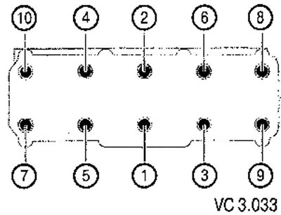
5. Tighten the cylinder head mounting bolts in 4 stages in the following sequence.
  • Pre-tighten with a torque wrench;
    • stage I: 35 Nm;
    • stage II: 60 Nm.
  • Tighten the screws with a regular wrench:
    • step III: Tighten an additional 1/4 turn (90°);
    • step IV: Turn an additional 1/4 turn (90°).
step IV: Turn an additional 1/4 turn (90°).


Attention! Perform additional tightening of the cylinder head mounting screws (after a run, as is done in some cars) not required.


Further installation is carried out in reverse order. In this case, the following should be noted.

6. After installing the cylinder head, turn the camshaft toothed pulley so that the pair of cams of the first cylinder are equally directed upward.
6. After installing the cylinder head, turn the camshaft toothed pulley so that the pair of cams of…


7. Before installing the timing belt, turn the crankshaft in the working direction and set it to the TDC position of the first cylinder.

8. Install the camshaft timing pulley hub.

9. Install the timing belt.

10. Install the poly V-belt.

11. Install the pressure oil line.

12. Install the soundproofing casing.

13. Install the water drainage box shield.

14. Fill with coolant.

15. Perform a test drive and then interrogate the engine control unit fault memory.

This article is available at russian, bulgarian, belarusian, ukrainian, serbian, croatian, romanian, polish, slovak, hungarian
The text has been checked: Kolesnikov Artem

Share information:

Previous articles
Installing the valve cover
Checking the cylinder head for warpage
List of parts and assemblies of the cylinder head
Cylinder head for diesel engines 1.9 and 2.0 l BDJ, BST, BJB, BSU, BLS
Cylinder head gasket markings
Measuring the protrusion of pistons from the cylinder block at TDC
Next articles
Camshaft, valves and pump-injector drive
List of components and parts of the valve mechanism
Checking the axial run-out of the camshaft
Valve sizes
Removal and installation the camshaft


Similar articles from other manuals for VW cars:
Removal and installation the cylinder head Passat B3 (1988-1993)
Cylinder head Golf 1 (1974-1984, petrol)
Cylinder head Polo 3 (1995-2003)
Removal and installation the cylinder head cover Touareg 1 (2002-2006)
Cylinder head Tiguan 1 (2007-2015)
Removal the cylinder head Sharan 1 (1995-2000)
Removal and installation the cylinder head (petrol 4-cylinder) Transporter T4 (1990-2003)
Link to this page in different formats


Visitor comments


No comments yet


How much will 12 + 43 =


Caddy 3 
  • General information
  • User manual
  • Daily care
  • Maintenance
  • Petrol engines 1.4 l
  • Engine repair
  • Cooling and lubrication system
  • Power and exhaust system
  • Petrol engines 1.6 l
  • Engine repair
  • Cooling and lubrication system
  • Power and exhaust system
  • Diesel engines
  • Engine repair
  • Cooling and lubrication system
  • Power and exhaust system
  • Transmission
  • Mechanical gearbox 0AH
  • Mechanical gearbox 0A4
  • Drive shafts
  • Chassis
  • Car suspension
  • Steering
  • Brake system
  • Body and wiring diagrams
  • Interior and exterior
  • Electrical circuits
Beetle 
  • General information
  • Maintenance
  • Power unit
  • Engine repair
  • Cooling and lubrication system
  • Supply system
  • Exhaust system
  • Transmission
  • Clutch
  • Car gearbox
  • Chassis
  • Front suspension
  • Rear suspension
  • Steering
  • Brake system
  • Wheels and tires
  • Body
  • Exterior
  • Electrical equipment
  • Equipment and devices
  • Power devices
  • Electrical circuits
LT 2D 
  • General information
  • User manual
  • Maintenance
  • Power unit
  • Petrol engines 2.3 l
  • Diesel engines 2.5 l
  • Diesel engines 2.8 l
  • Injection system (diesel 2.8 l)
  • Transmission
  • Clutch
  • Manual gearbox
  • Differential
  • Chassis
  • Car suspension
  • Steering system
  • Brake system
  • Body
  • Body elements
  • Heating system
  • Electrical equipment
  • Equipment and devices
  • Electrical circuits
LT 28 
  • General information
  • Maintenance
  • Power unit
  • Petrol engines 2.0L
  • Petrol engines 2.4L
  • Diesel engines
  • Cooling and heating
  • Fuel and exhaust system
  • Ignition system
  • Transmission
  • Clutch
  • Car gearbox
  • Cardan shaft
  • Rear axle
  • Chassis
  • Brake system
  • Car suspension
  • Steering system
  • Body
  • Body elements
  • Doors, locks and windows
  • Electrical equipment
  • Power devices
  • Equipment and devices
  • Electrical circuits
VWmanual.ru © 2016-2026 | Mobile version | News and articles | Sitemap: EN BG BY UA RS HR RO PL SK HU | Write message | Site search
Passat B2 • Passat B3 • Passat B4 • Passat B5 • Passat B6 • Golf 1, diesel • Golf 1, petrol • Golf 2, petrol • Golf 2 • Golf 3 • Golf 4 • Golf 5 • Polo 3 • Polo 4 • Touareg 1 • Tiguan 1 • Sharan 1 • Transporter T3 • Transporter T4 • LT 28 • LT 2D • Beetle • Caddy 3 •
Our website uses cookies to ensure functionality and convenience.