
Removing
1. Remove the toothed belt from the camshaft pulley.
2. Remove the retainer.
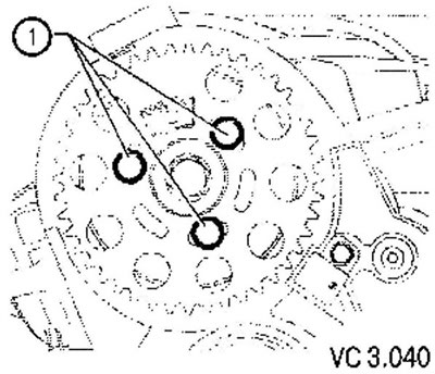
3. Remove fixing screws (1) fastening the camshaft pulley.
4. Remove the toothed pulley from the hub.
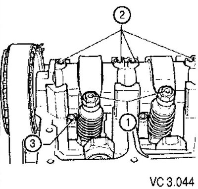
5. Loosen the screw (1) camshaft hub mounting.
6. To do this, use the camshaft holding tool.
7. Loosen the hub fixing screw approximately 2 turns.
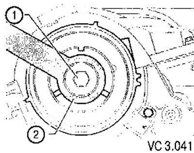
8. Remove the hub from the camshaft taper using a puller.
9. To remove a cover of a head of the block of cylinders.
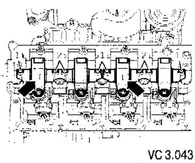
10. Mark the axes of the rocker arms with a waterproof felt-tip pen so as not to confuse them in the future. Otherwise, it may be necessary to adjust the position of the unit injectors (arrows).
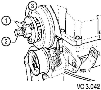
11. Loosen the locknuts of the adjusting screws (1) and unscrew the adjusting screws.
12. Unscrew the fastening screws (2) axes of the rocker arms sequentially from external to internal and remove the axle of the rocker arms of the pump-injector drive.
13. Remove the double pump.
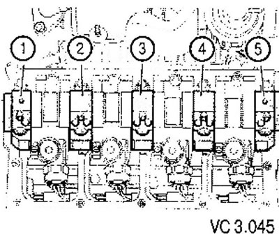
14. Remove covers first (5), (1) And (3). In turn, crosswise release the covers of the supports (2) And (4).
15. Remove the camshaft.
Installation
Attention: before proceeding with the installation of the camshaft, the following conditions must be met:
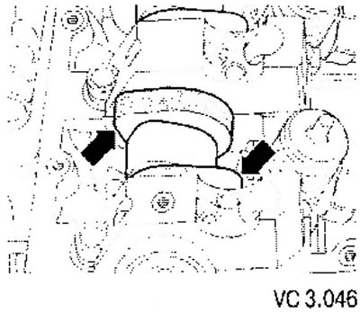
- When installing the camshaft, the cams for the first cylinder (arrows) should be directed upwards.
- Previously used bearing shells must not be interchanged (mark when removing).
- When installing the camshaft, pay attention to the fact that the retaining tabs of the liners installed in the cylinder block of the cover must be located opposite each other.
- Before installing the covers, make sure that the washers of the cylinder head screws are installed in the head of the block.
- Lubricate the working surfaces of the liners.
1. Install the support covers (2) And (4), by fixing them with new screws (see fig. VC 2.045).
2. Tighten the cover screws (2) And (4) alternately crosswise with a torque of 8 Nm, and then tighten them 1/4 turn (90’).
3. Install the support covers (5), (1) And (3), by securing them with new screws.
4. On the seating surfaces of the bearing caps (1) And (5) apply sealant.
5. Support cover (5) must not form a ledge with the edge of the cylinder head, otherwise there may be a leakage in the double pump.
6. Tighten the cover screws (5), (1) And (3) torque of 8 Nm, and then tighten them 1/4 rev. (90°).
7. Install the camshaft seal.
8. Tighten the fastening screw (1) camshaft hub torque 100 Nm (see fig. VC3.040).
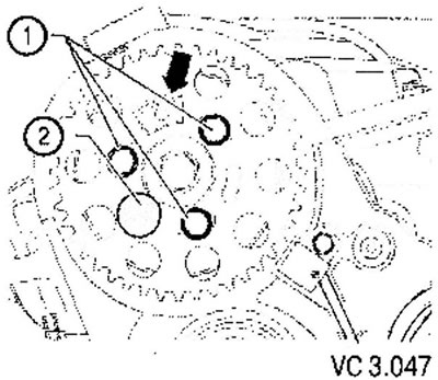
Attention! Toothed segment (arrow) the camshaft pulley must be at the top.
9. Install the hub on the camshaft.
10. Tighten the fastening screw (1) hub torque 100 Nm.
11. Install the camshaft sprocket onto the hub.
12. Install the pulley so that the mounting screws are in the middle of the concentric grooves.
13. Screw in the fixing screws (1) by hand until it stops 8 camshaft pulley.
14. Fix the hub. Install toothed belt and adjust valve timing.
Attention! After each removal of the rocker shaft and for each work requiring adjustment of the unit injectors, it is necessary to replace the adjusting screws and ball pins of the unit injectors.
15. Install the rocker shafts with new adjusting screws and tighten the new fastening screws as follows:
- Tighten first the inner and then the outer fastening screws evenly and crosswise. Torque; 20 Nm + tighten 1/4 turn (90°).
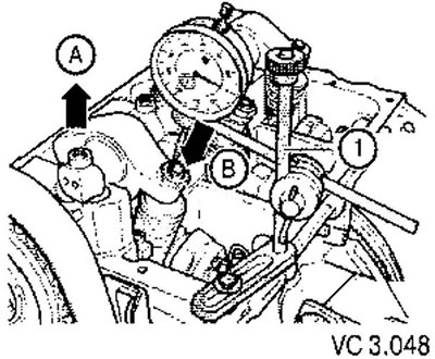
16. Install the dial indicator as shown in the figure on the adjusting screw of the unit injector.
17. Rotate the crankshaft in the direction of engine rotation until the rocker roller is on top of the drive cam. Video clip (arrow A) is at its highest point, the indicator (arrow B) - at the bottom.
18. Remove the dial gauge.
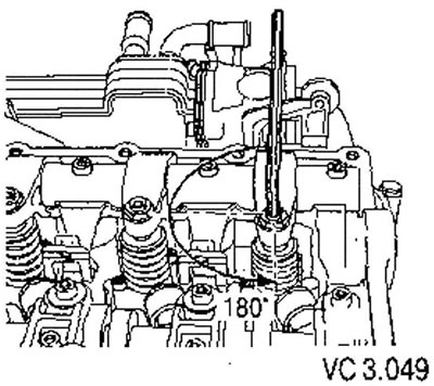
19. Screw the adjusting screw into the rocker until a clear resistance is felt (tappet clearance selected).
20. Turn the adjusting screw back by 180°.
21. While holding the adjusting screw in this position, tighten the locknut to 30 Nm.
22. Install the cylinder head cover.
23. Install the double pump.
Attention! After installing new hydraulic lifters, do not start the engine for about 30 minutes. Hydraulic lifters must have time to compress (otherwise, the partially open valves will collide with the pistons).
Visitor comments