



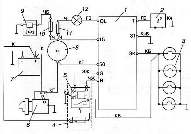
Fig. 3-50. Electrical diagram of the engine preheating system "1Y", "RA", "SB", "AAZ":
1 - battery;
2 - starter;
3 - spark plug;
4 - starting spark plug;
5 — pre-heating indicator lamp;
6 — pre-heating control unit;
7 — fuel shut-off valve;
8 — spark plug relay;
9 - coolant temperature sensor;
10 - fuse No.15 of the fuel shut-off valve (10 A);
11 - fuse No.15 (10 A) on the instrument panel;
12 — fuse (15 A) of starting plugs.
Wire color designation:
B - white;
G - blue;
Y - yellow;
3 - green;
K - red;
Kch - brown;
Ch - black.
the letter indicates the color of the wire itself, the second one indicates the color of the stripe on the wire
Voltage is supplied to the starting plugs when the instrument and starter switch key is set to the "Pre-heating" or "Starter" position, and is disconnected when the key is in the operating position. The driver sets the key to the "Starter" position only after the pre-heating time has expired, otherwise the engine may not start.
Visitor comments