
Checking the ignition coil
It is carried out similarly to the test for engines with a volume of 1.3 liters, however, the resistance of the primary and secondary windings is different for them (see table. 9).
Table 9. Resistance of the windings of the ignition coils
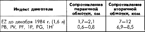
1 Gray sticker on the ignition coil.
Checking the ignition distributor slider
Checking the ignition distributor slider is carried out in the same way as for 1.3-liter engines, however, the resistance of the slider is as follows: for engines with a volume of 1.6 liters of production until December 1984 - (5+1) kOhm, for engines 1.6 and 1.8 l, after January 1985 - 1 kOhm (slider marking R1).
Checking the knock sensor and control unit
For verification, only a voltage probe with an LED is required. Do not use a tester with a conventional test lamp, as the electronic ignition system may be damaged due to high consumption.
Connect the voltage tester to the control socket (single pin connector with blue wire) and to the positive battery terminal. The voltage probe LED should light up.
Start the engine. Increase the speed to 3000 rpm. The voltage probe LED should turn off. Then check the ignition timing.
If the LED does not go out, connect an auxiliary wire to the connector and short it for at least 5 seconds for «mass». After that, the constant glow of the LED should turn into flashing. In this case, the VEZ control unit starts to issue a fault code. Double flashing at intervals means: a defect in the knock sensor or the VEZ control unit.
Turn off the engine and ignition.
Search for broken wires, check the contacts for corrosion.
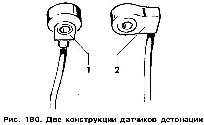
Check the torque of the knock sensor. Knock sensors of two designs can be installed (pic. 180). The tightening torque of the sensor depends on its design and must be strictly observed. Loosen the knock sensor mount and tighten the mount with a torque wrench to the prescribed value. Design 1:15 - 20 Nm, design 2:10 - 12 Nm.
Flashing the LED three times at intervals indicates a leak in the hose connected to the VEZ control unit, or a failure of the VEZ control unit. Check the tightness of the vacuum hose and its connection to the VEZ control unit.
Repeat check. If the fault code continues to be set, check and, if necessary, replace the control unit (work is done at the service station).
Checking the lead angle (moment) ignition
A strobe is required for verification. Connect the stroboscope according to its instruction manual.
Check ignition timing at idle (see table. eleven «lead angle (moment) ignition»).
With the engine running, disconnect the vacuum hose from the VEZ control unit and increase the engine speed.
Check ignition timing relative to idle (tab. 10).
Table 10. Lead angle (moment) ignition at high engine speed
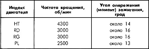
Table 11. Lead angle (moment) ignition

1 With hydraulic support.
2 The temperature sensor connector is disconnected.
3 With automatic transmission (950±50) rpm
4 When refueling with unleaded petrol (octane number 95) (14±1) °to TDC.
5 When refueling with unleaded petrol (octane number 95) (0±1) °to TDC.
6 Not regulated.
7 The hose from the two-way valve is a device for increasing the speed but is pinched at idle.
Visitor comments