
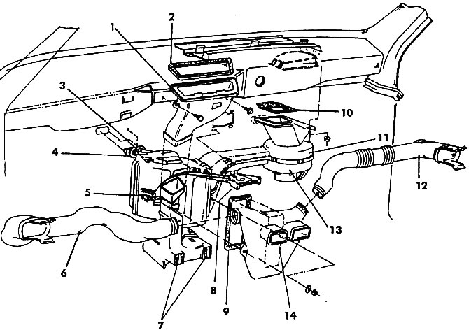
Pic. 106. Scheme of the heating and ventilation system of the cabin: 1 - windshield air duct, 2 - gasket, 3 - heater core, 4 - gasket (must be replaced each time), 5 - heater cover, 6 - left air duct, 7 - foot air nozzles, 8 - heating, ventilation and temperature control levers, 9 - gasket, 10 - gasket, 11 - air duct, 12 - right air duct, 13 - fan, 14 - distribution casing
General recommendations for repair
The warm air distributor, air ducts, control levers and the rods connected to them are dismantled as a whole.
All inspection and repair operations are carried out without the use of great force. It should be remembered that plastic parts are quite fragile and can be easily damaged.
Operations related to the heating and ventilation control levers will be described below. The procedure for removing and installing the central air ducts will be described below.
If the air distributor must be dismantled in order to replace the heater, follow the instructions below.
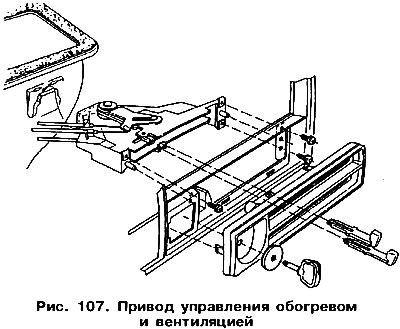
On fig. 107 shows a diagram of the heating and ventilation control drive. This unit is removed together with the rods through the central air outlet of the distribution panel. Three rods must be disconnected from the air distributor. The decorative overlay of the heating control levers is removed after being released from the side latches. Installation is in the reverse order. Adjustment of rods is carried out as described below. The rods have different colors to make them easy to distinguish. Before adjustment, all rods should be connected to the control levers, while the black long and short rods are connected to the heating and ventilation control lever.
Insert the shells of the rods into the holders (arrows in fig. 108).
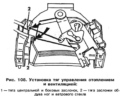
black long pull 1 (pic. 108) connect to the lever that controls the center and side flaps.
Connect the black short rod 2 to the lever that controls the blowing of the legs and the windshield.
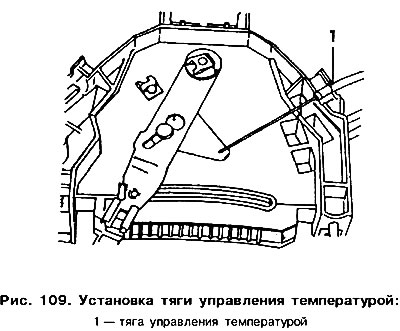
traction 1 (pic. 109) connect to the lever that controls the air temperature.
Install the control unit and move both levers to the left, that is, close the heater valve and hot air channels and open the cold air supply.
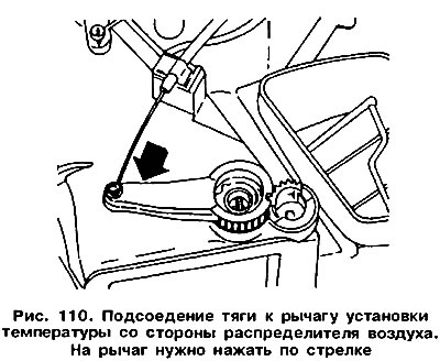
Connect the black long rod on the other side to the central damper lever mounted on the air distributor. Push the lever in the direction of the arrow (pic. 110) and remove the protective sleeves.
Attach the black short rod on the other side to the leg and windshield damper lever mounted on the air distributor, as shown in fig. 111.
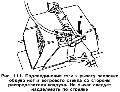
Move the lever in the direction of the arrow and insert the safety sleeves on both sides.
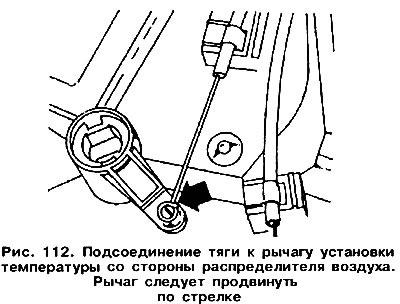
Connect the blue rod to the damper that regulates the temperature (pic. 112). Push the lever (arrow) and insert the safety bushings of the traction sheath.
After connecting the rods, alternately move the heating, ventilation and temperature control levers. You should be able to hear the dampers hitting the stoppers.
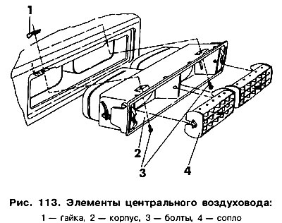
Elements of the central air duct are shown in fig. 113. On the basis of this scheme, perform all actions for their removal and installation. The side nozzles have a similar design.
On fig. 114 shows the components of the air distributor. Having disconnected the control levers, unbent the heater clamps, it is possible to divide the distributor casing into two parts and remove the remaining parts. If during assembly the clamps do not fix the distributor housing, it can be connected with two self-tapping screws, which should be screwed into the upper housing.
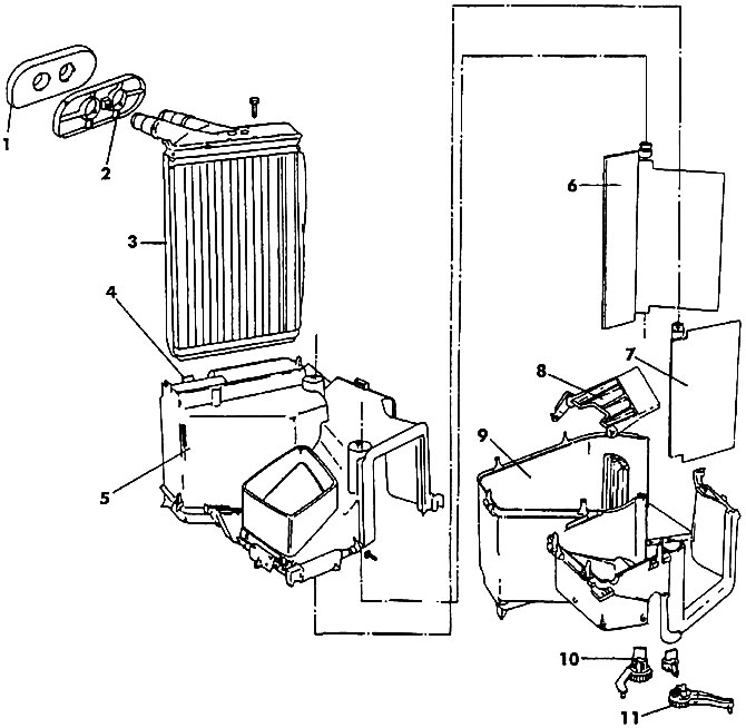
Pic. 114. Heater casing: 1 - gasket, 2 - cover, 3 - radiator, 4 - clip, 5 - upper part of the casing, 6 - temperature control damper, 7 - central damper, 8 - damper with lever that regulates the airflow of legs and windshield, 9 - lower part casing, 10 - temperature control damper lever, 11 - central and side damper lever
Visitor comments