
Remove the key from the groove of the rotor shaft.
Loosen the screws and remove the regulator 10 (pic. 437) voltage together with the brush holder. Mark the relative position of the covers and unscrew both coupling bolts. Detach the front cover from the back. In this case, you can help with a plastic hammer, lightly tapping on the front cover.
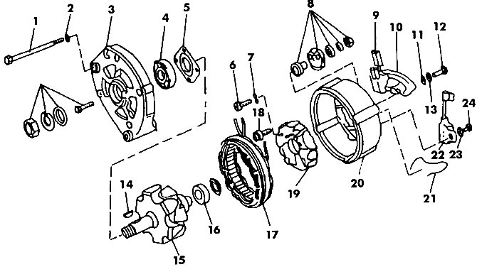
Pic. 437. BOSCH generator components: 1 - coupling bolt; 2, 11 - washers; 3 - front cover; 4, 16 - ball bearings; 5 - bearing mounting plate; 6, 12, 18, 24 - bolts; 7, 13, 22 - spring washers; 8 - contact bolt; 9 - carbon brush; 10 - voltage regulator; 14 - key; 15 - rotor; 17 - stator; 19 - rectifier board; 20 - back cover of the generator; 21 - spring; 22 - capacitor
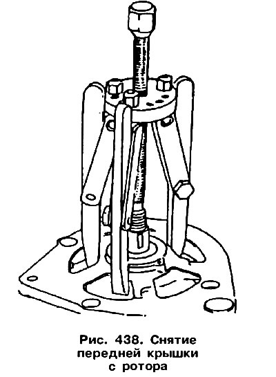
Place the front cover of the generator together with the rotor under the press. Using a three-jaw puller, remove the cover from the rotor (pic. 438). During the removal of the rotor, there is a danger of stripping the bolts of the bearing plate. Therefore, the grips of the puller must be placed under the bearing plate, and not just under the cover. If you need to remove the bearing from the front cover, you must unscrew and knock out the bearing.
It is necessary to remove the bearing from the rotor from the side of the slip rings. Using a puller, you need to capture the inner race of the bearing.
Unsolder the board with diodes from the generator, while avoiding overheating of the diodes.
Attention! Rectifier diodes should only be dismantled by professionally trained persons with special tools.
Check that the carbon brushes fit well on the commutator and that they move freely in the brush holder. Clean the brush holder if necessary.
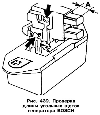
Brushes must be replaced if their length has decreased to 5.0 mm (size «A» in fig. 439). The arrows in the figure indicate where the brushes are soldered.
Contact rings should be cleaned with a cloth soaked in a special liquid. Small scratches can be removed with very fine sandpaper.
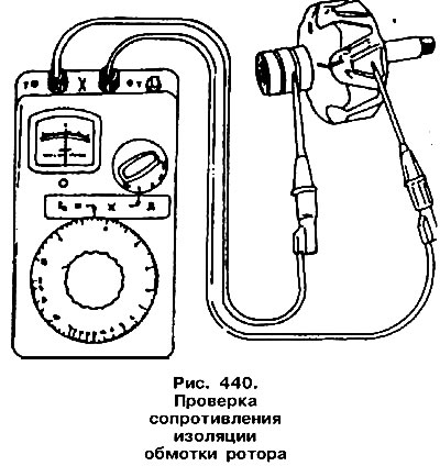
To check the insulation resistance of the rotor, one end of the multimeter should be attached to the rotor housing, and the other to the slip ring (pic. 440). If the device does not show «infinity», the rotor needs to be replaced. To check the integrity of the winding, both contacts of the multimeter should be attached to the slip rings (pic. 441). The device should show 3.4-3.75 ohms for a generator with a recoil current of 45 A or 2.8-3.0 for a generator with a recoil current of 65 A.
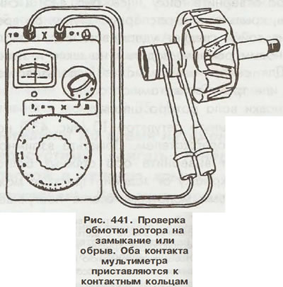
Indication «infinity» means the presence of a break in the winding, and other values - a short circuit. In both cases, the rotor must be replaced.
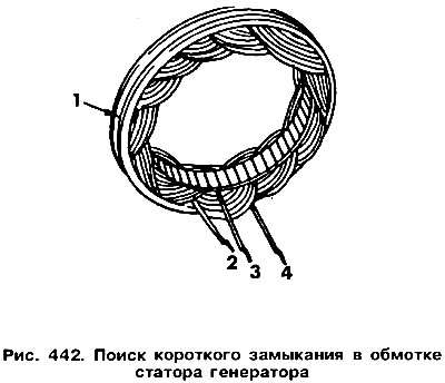
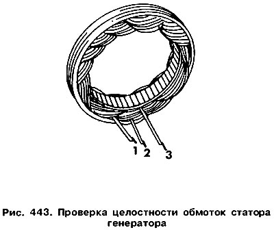
A short circuit in the stator winding is manifested in a strong heating of the winding. To determine the presence of a short circuit, one contact of the multimeter should be applied to the outer, stator ring, and the other end in turn to the three stator terminals (pic. 442). With a good winding, the device should show «infinity». To check the integrity of the stator winding, you need to connect the multimeter leads directly to two of the three wires, i.e. 1 and 2, 2 and 3, 1 and 3 (pic. 443). The winding resistance should be 0.18-0.20 ohms for a generator with a recoil current of 45 A or 0.1 0-0.11 ohms for a generator with a recoil current of 65 A. No readings and «infinity» indicate a break in the winding.
Checking the operation of diodes requires special equipment and should be carried out in a specialized workshop.
Visitor comments