



Contents: Tires ↓ Suspension ↓
The following maintenance steps must be performed on the chassis:
Tires
1. Check and, if necessary, adjust the tire pressure. Check the condition and general wear of the tires. If the wear is uneven, it is recommended to have the tires inspected at a workshop to adjust the suspension geometry.
Suspension
2. It is necessary to lift and place the car on supports, then inspect the parts that are part of the suspension and control system for signs of significant wear or damage. Check the ball joints 11 and suspension, paying attention to the existing gaps and the condition of the rubber covers for signs of cracks and damage. If necessary, replace these parts with new ones. Check the metal-rubber bushings 16 and 23, transverse 13 and stabilizer mounts 5 and 21, whether they are knocked out. If necessary, replace them with new ones. Check for signs of fluid leakage from the shock absorbers and traces of corrosion on the suspension element mounts to the auxiliary frame and body.
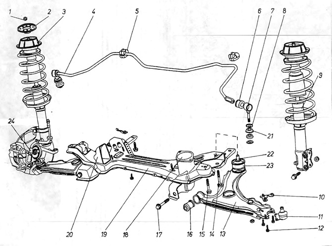
Figure 10.1. Front suspension
1 - column nut; 2 - mounting plate; 3 - spring column support; 4 - transverse stabilizer; 5 - cushion securing the stabilizer; 6 - rubber bushing; 7 - stabilizer connector; 8 - washer; 9 - steering rod (lever); 10 - Clamping washer of the hinge; 11 - ball joint of the steering knuckle; 12 - hinge bolts; 13 - lower balancer; 14 - bolt securing the rear metal-rubber bushing of the balancer; 15 - bolt securing the front metal-rubber bushing; 16 - metal-rubber bushing; 17 - lever axis; 18 - Gearbox suspension cushion bracket; 19 - auxiliary frame; 20 - Engine mount bracket; 21 - rubber cushions installed with a cone towards washers 8; 22 - metal bushing, removed during disassembly of the balancer; 23 - metal-rubber bushing; 24 - brake pipe.
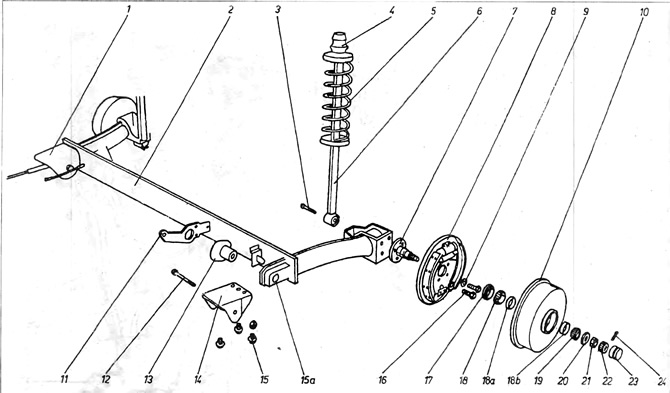
Figure 10.2. Rear suspension
1 - handbrake cable; 2 - rear suspension beam; 3 - bolt securing the shock absorber; 4 - rubber cushions; 5 suspension spring; 6 - shock absorber; 7 - hub axle; 8 - disc that holds the brake pads; 9 - washer; 10 - brake drum; 11 - Brake force corrector lever; 12 - rear beam bracket bolt; 13 - metal-rubber suspension bushing (shows the so-called protruding segment of the bushing, which can be turned towards the front of the vehicle during installation); 14 - beam bracket; 15 - bracket bolts; 16 - the hole in which the bushing 13 is seated; 17 - bolts securing the axle shaft to the suspension beam; 18 - inner bearing; 18a - inner bearing track; 18b - outer bearing track; 19 - outer bearing; 20 - washer; 21 - hub nut; 23 - safety ring; 22 - hub cap; 24 - check.
Visitor comments