
Instructions: The engine is removed together with the gearbox down. After installing the engine, it is necessary to reinstall all the cable ties that are removed or cut off during dismantling.
ATTENTION: When performing installation work, especially in the engine compartment due to its dense layout, the following rules must be observed. Highways of all types (e.g. fuel, hydraulic, activated carbon absorber, cooling system, air conditioning circuit, brake system, vacuum), as well as electrical wires must be laid so. how they were originally laid out. Sufficient space must be provided when working on all moving or hot parts.
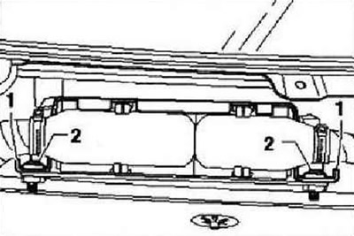
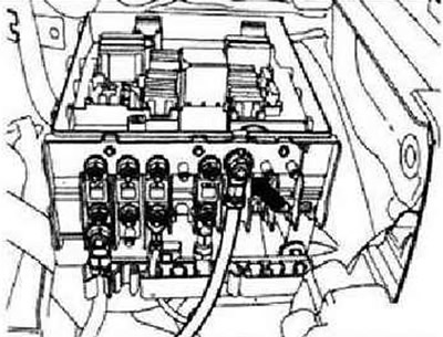
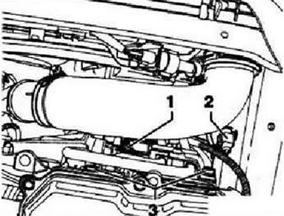
With the ignition off, disconnect the ground wire from the battery. Remove the battery and battery mounting pad. Remove engine cover. Remove air filter housing with air mass meter and connecting tube. Remove fuel filter and additional fuel pump -V393-. Extract the refrigerant from the air conditioner circuit. Remove the sound absorbing tray. Remove wiper arms. Remove the plenum box cover. Remove the plastic cover over the engine control unit. Bend upwardly protruding ends -1- of retaining clip outwards. Unscrew shear bolts -2- with a hand vise and remove retaining clip.
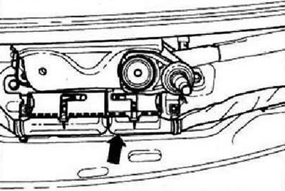
Disconnect wiring harness connector -arrow- from engine control unit.
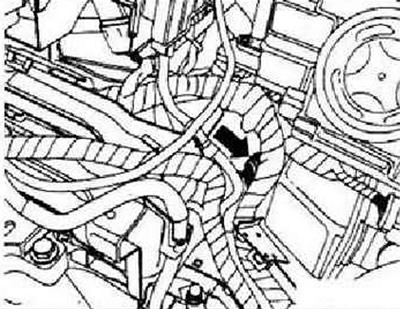
Unlock the cable duct locks on the side member. Disconnect the electrical connector -arrow- of the engine wiring harness below the left headlight. Remove the engine wiring harness from the cable duct and place it on the engine.
Unplug connector -1- and unscrew earth cable -2- from side member.
Unscrew the positive starter cable -arrow- from the onboard power supply control unit and place it on the engine.
With dual clutch gearbox
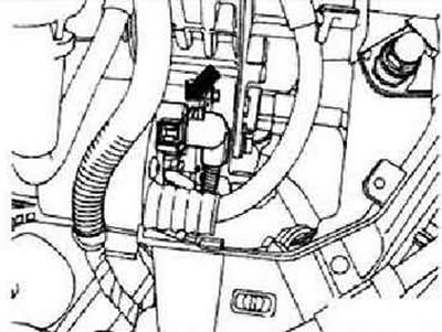
Remove the control lever from the gearbox. Unlock lock on mechatronic connector -arrow- by turning and disconnect connector.
With manual transmission
Remove the control lever from the gearbox. Remove the hose line or plastic line from the clutch slave cylinder.
With automatic transmission
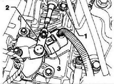
Remove the control lever from the gearbox. Unplug connector -3- at gearbox. Items 1 and 2 are ignored.
Disconnect connector -arrow- from starter.
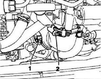
Disconnect connectors -1- and -2- and unscrew the screws securing the lines to the gearbox oil cooler -3-. Disconnect the pipes from the oil cooler on the gearbox, collect the oil that flows out.
All
Unscrew air conditioner circuit lines -arrows- from air conditioner compressor.
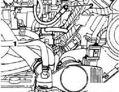
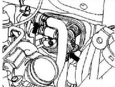
Disconnect connector -1-, loosen clamp -2- and detach connecting hose. Remove the boost pressure control valve from the front wall of the plenum box and lay it together with the vacuum lines on the engine. Disconnect vacuum line from vacuum pump. Remove subframe with steering gear. Disconnect drive shafts from gearbox.
Remove particulate filter.
All wheel drive vehicles
Remove the rear of the exhaust system. Remove the rear axle drive shaft.
All
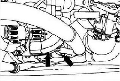
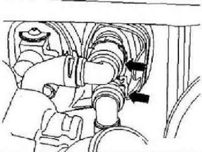
Drain coolant. Disconnect the lower charge air pipes from the intercooler. Disconnect the quick fittings on the radiator. Disconnect the quick-release fittings from the heat exchanger -arrows- on the front wall of the plenum box. Remove the noise insulation from the oil pan. Loosen the screws securing the charge air pipe leading to the air damper and remove it.
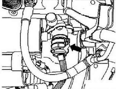
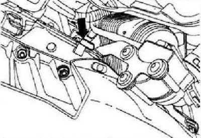
Unscrew securing bolt -arrow- for coolant bleeder pump after switching off. engine.
Attach bracket -T10012- to cylinder block with nut and bolt M10x25, strength class 8.8, tightening torque 40 Nm. Fit bracket -T10012- to jack -VAG 1383 A-. Slightly raise the cistern using the engine jack -VAG 1383 A-.
Instructions: Loosen securing bolts from ladder -VAS 5085-.
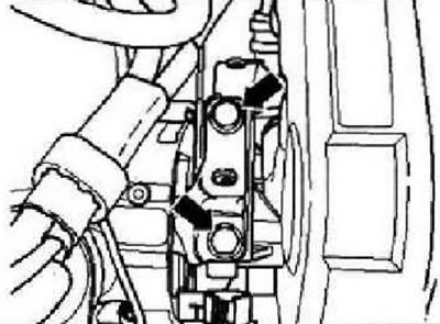
Remove bolts from above connecting power unit support on engine side to engine support -arrows-.
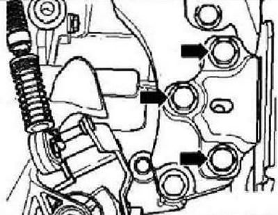
Remove bolts securing power unit support to gearbox bracket from above -arrows-.
Carefully lower the engine from the gearbox.
Instructions: Lower the power unit carefully to avoid damage to the body.
Visitor comments