



- remove the distributor cap;
- disconnect the Hall sensor connector from the ignition distributor. To do this, squeeze the spring clamp and pull out the connector;
- crank the engine until the piston of the first cylinder reaches the TDC position of the compression stroke:

Fig. 219. Engine TDC position: A - on the engine installed on the vehicle; B - on the engine removed from the vehicle
- on the engine installed on the car, the mark "0" (fig. 219, A) on the flywheel should be in line with the edge of the "window" in the flywheel housing;

Fig. 220. Location of the mark on the outer side of the camshaft gear when the piston of the first cylinder is set to the TDC position of the compression stroke
- on the removed engine, the groove on the vibration damper should coincide with the arrow on the protective cover of the drive belt (fig. 219, B), and the adjustment mark on the camshaft pulley (Fig. 220) should be in line with the arrow on the drive belt cover.

Fig. 221. Places of application of marks on the runner and the edge of the ignition distributor housing
- install the distributor rotor in the position shown (Fig. 221) before removing it. Mark the top of the rotor and the edge of the distributor housing by scratching;
- place a socket head on the vibration damper bolt to turn the engine.
- unscrew the bolt and remove the ignition distributor clamping rail;
- remove the ignition distributor from the engine.
The ignition distributor is installed in the reverse order of removal.
If the engine was turned after removing the ignition distributor, do the following:
- on the engine installed on the vehicle:
- set the piston of the first cylinder to the TDC position during compression, i.e. both valves should be closed (if the cylinder head cover is removed), or turn the engine until the mark is "0" (fig. 219, a) on the flywheel will not be in line with the edge of the "window" in the flywheel housing;
- on the engine removed from the car:
- crank the engine until the groove on the vibration damper aligns with the arrow on the drive belt guard (fig. 219, B), in this case, the adjustment mark on the outer side of the camshaft gear should lie opposite the TDC mark located on the inner metal wall (Fig. 220);

Fig. 222. Aligning the oil pump shaft receiving journal before installing the ignition distributor. The journal axis runs parallel to the crankshaft axis
- check the position of the oil pump shaft journal. The journal axis (Fig. 222) should be parallel to the crankshaft axis. If necessary, the shaft journal can be aligned using pliers;
- orient the distributor runner according to the previously applied marks on the runner and on the edge of the distributor housing (Fig. 221);
- in this position of the runner, put on the distributor cap and secure it with clamps;
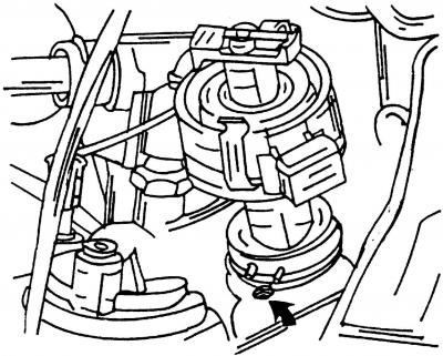
Fig. 223. Installing the ignition distributor
- orient the ignition distributor (fig. 223, shown by arrow) and install it on the engine;
- connect the three-pin plug connector of the ignition distributor;
- adjust the ignition timing (see subsection 8.6), by turning the ignition distributor housing.
We recommend that you contact a service station to conduct a precise check and adjustment of the ignition timing, which is carried out using a special tool.
Visitor comments